


OM-217 Page 17
Panel
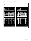
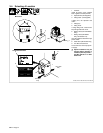
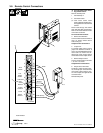
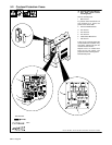
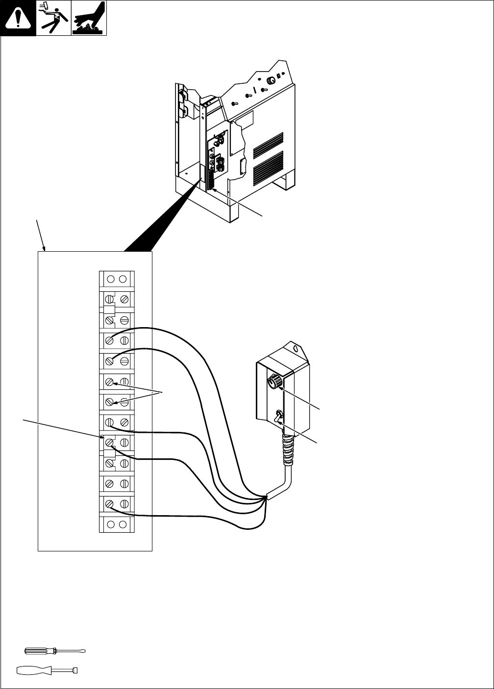
3-8. Remote Control Connections
Ref. ST-159 466-C / Ref. ST-150 802-A
Y Turn Off power before instal-
ling remote control.
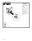
Remove left side panel.
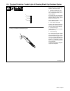
1 Terminal Strip 1T
2 Connection Label
. Lead colors shown match
those of Remote Pendant Con-
trol supplied with machine-held
torches.
Route leads through hole below
torch and work cable access holes.
Refer to connection label and make
connections as follows:
Torch On/Off Connections:
3 Remote On/Off Switch
Connect switch leads to terminals 3
and 4 as shown. Switch closure
starts cutting arc.
Output Control Connections:
4 Jumper Link
For remote output control, remove
jumper link between terminals 9
and 10, and reinstall between termi-
nals 8 and 9 as shown. This dis-
ables front panel Output Control
and enables remote output control.
5 Remote Output Control
Connect control leads to terminals
7, 8, and 11 as shown.
Output Sensor Connections:
6 Output Sensor Terminals
Terminals 5 and 6 connect to inter-
nal, normally-open contacts which
close when cutting output is pres-
ent. For example, use signal to start
automatic fixture.
Reinstall side panel.
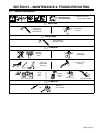
Tools Needed:
3/8 in
2
1
1
2
3
4
5
6
7
8
9
10
11
71
72
84
85
64
63
65
66
70
43
3
5
4
6
S-169 259
N.O.
Output
Sensor
Command
Ref.
Remote
Jumper
Common
Signal
Ground
Torch
Switch
+10 Volts DC
(Brown)
Black
White
Wiper (Red)
GND (Green)
1T