


OM-217 Page 20
SECTION 4 – OPERATION
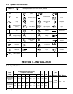
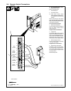
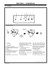
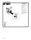
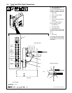
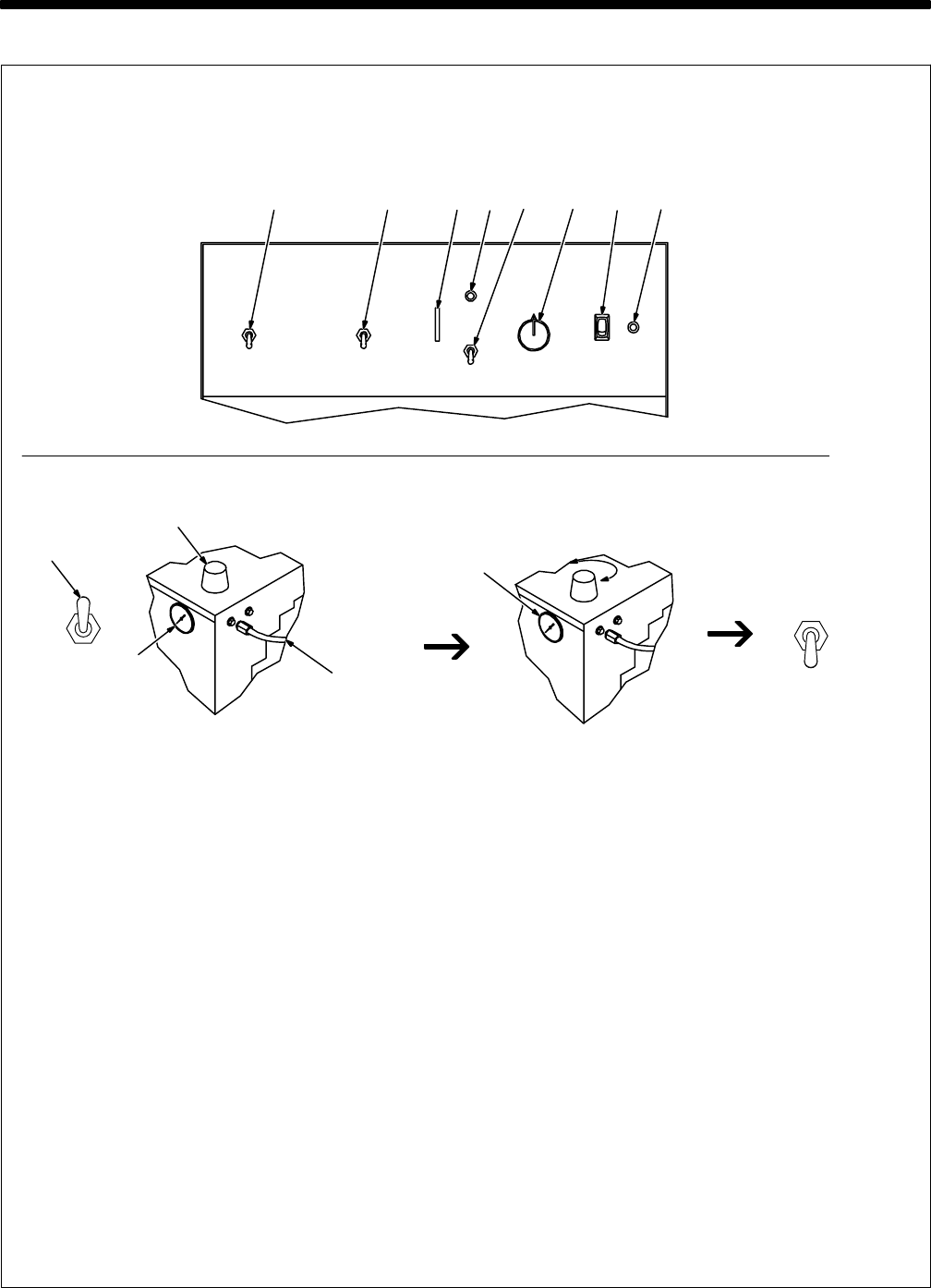
4-1. Controls
Ref. ST-159 465-A / ST-800 701 / S-0818
12345678
1 Pilot Light
2 Power Switch
3 Output Control
Use control to set cutting output.
For non-shielded cutting, use a 1/8 in (3 mm)
standoff distance between torch tip and
workpiece.
4 Set/Run Switch
Place switch up to safely adjust gas/air pres-
sure. Only gas/air circuit is activated.
Place switch down to cut or gouge.
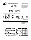
5 Ready Light
Use light to tell if unit is ready for operation.
Ready light comes on when Power switch is
placed in On position, indicating that all safe-
ty shutdown systems are okay.
If Ready light does not come on, check
Trouble Lights.
6 Trouble Lights (See Section 5-3)
7 Trigger Hold Switch
To cut without holding torch trigger, place
switch up, and begin cutting by pressing and
releasing torch trigger. To stop cutting, press
and release trigger.
When set in down position, trigger must be
held closed while cutting.
8 Pilot Arc Control Switch
Place switch down for pulsed pilot arc
output. Use this position whenever possible
to reduce wear on torch and consumables.
Place switch up for a continuous pilot arc.
Use this position when cutting starts are
critical or while cutting expanded metals.
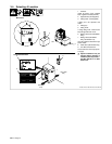
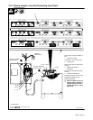
Setting Gas/Air Pressure
9 Air Filter/Regulator
10 Pressure Adjustment Knob
Place Set/Run switch up and turn on gas/air
supply. Lift knob and turn to adjust pressure.
Push knob down to lock in setting.
Place Set/Run switch down to begin cutting.
Requires
80-150 psi
(552-1034 kPa)
Supply
9
10
Setting Gas/Air Pressure
4
Set To 70 psi
(482 kPa)