


OM-217 Page 25
1T
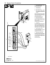
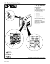
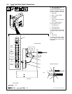
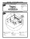
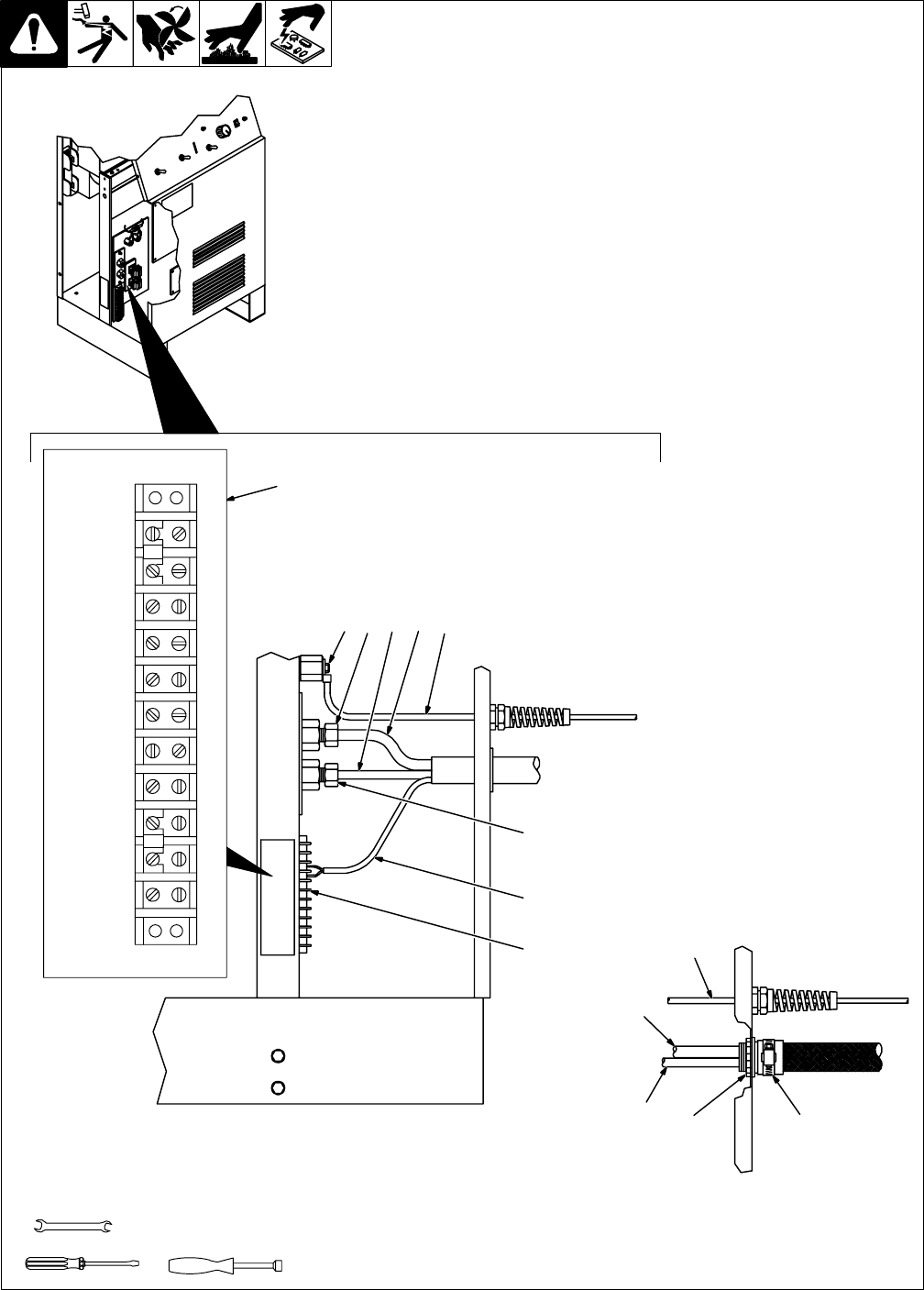
5-5. Torch And Work Cable Connections
Y Turn Off power before re-
moving side panel.
If torch or work cable needs to be
removed or replaced, remove left
side panel, and proceed as follows:
1 Work Cable
2 Work (+) Output Terminal
3 Torch Cable
4 Pilot Cable
5 Torch (–) And Gas/Air Output
Connector
6 Pilot (+) Output Terminal
Connect cables as shown.
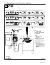
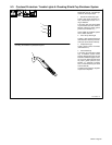
7 Terminal Strip 1T
8 Connection Label
9 Torch Switch Leads
For hand-held torches, refer to label
to connect leads. Reinstall side
panel.
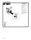
10 Nut
11 Hose Clamp
For machine-held torches, tighten
nut and clamp to secure cables.
See Section 3-8 for remote control
connections.
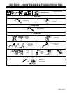
Tools Needed:
Ref. ST-159 466-C / ST-800 702-B
3/8 in
1/2 in
8
7
5
7
2431
1
2
3
4
5
6
7
8
9
10
11
71
72
84
85
64
63
65
66
70
43
9
6
1
3
4
1110
Hand-Held Torch
Machine-Held Torch
Side View
OR
Panel
N.O.
Output
Sensor
Command
Ref.
Remote
Jumper Com-
mon
1T
Torch
Switch
S-169 259
Signal
Ground