


OM-217 Page 19
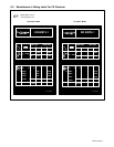
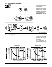
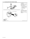
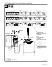
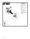
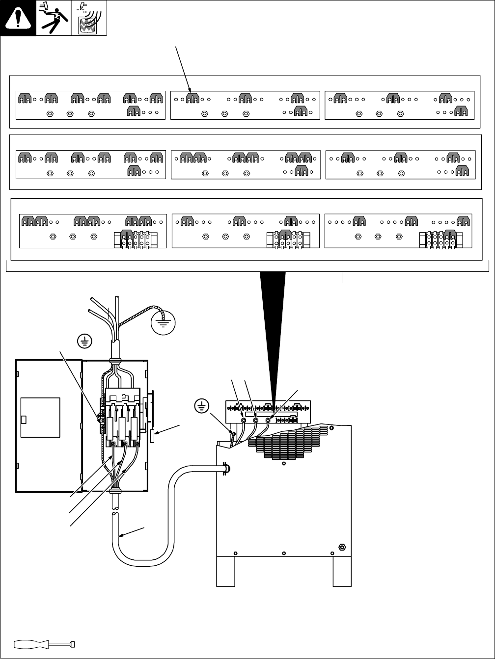
3-10. Placing Jumper Links And Connecting Input Power
Ref. ST-800 718
Check input voltage available at
site.
1 Jumper Link Label
Check label – only one is on unit.
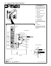
2 Jumper Links
Move jumper links to match input
voltage.
3 Input And Grounding
Conductors
Select size and length using Sec-
tion 3-9.
4 Line Disconnect Device
Select type and size of overcurrent
protection using Section 3-9.
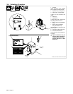
Reinstall side panel.
Y Special installation may be
required where gasoline or
volatile liquids are present –
see NEC Article 511 or CEC
Section 20.
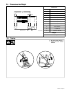
Tools Needed:
4
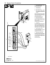
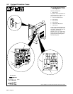
230 VOLTS
S-012 242-A
L1 L2 L3
460 VOLTS
L1 L2 L3
575 VOLTS
L1 L2 L3
1
200 VOLTS
S-031 770-A
L1 L2 L3
230 VOLTS
L1 L2 L3
460 VOLTS
L1 L2 L3
L1 (U)
L2 (V)
GND/PE
Earth Ground
L3 (W)
Connect GND/PE
Conductor First
3/8, 7/12, 1/2 in
L3 (W)
2
Connect GND/PE
Conductor First
L1 (U) L2 (V)
3
1
220 VOLTS
S-151 770
L1 L2 L3
380 VOLTS
L1 L2 L3
415 VOLTS
L1 L2 L3