


. A complete Parts List is available at www.MillerWelds.com
OM-201 872 Page 13
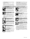
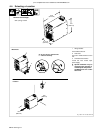
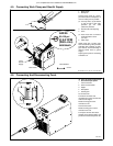
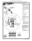
4-5. Connecting Work Clamp and Gas/Air Supply
1 Work Clamp
2 Workpiece
Connect work clamp to a clean,
paint-free location on workpiece, as
close to cutting area as possible.
. Use only clean, dry air with 90
to 120 psi (621 to 827 kPa)
pressure @ 9.2 CFM
(260L/min) minimum.
3 Gas/Air Filter Inlet Opening
4 Hose
. Hose must have a minimum
inside diameter of 3/8 in
(9.5 mm).
5 Teflon Tape
Obtain hose with 1/4 NPT right-
hand thread fitting. Wrap threads
with teflon tape (optional) or apply
pipe sealant, and install fitting in
opening. Route hose to gas/air
supply.
Adjust gas/air pressure according
to Section 5-2.
Tools Needed:
9/16 in
3
4
Ref. 803 640-A / Ref. 192 441 / Ref. 804 026-A
Rear of Unit
5
1
2
From
Gas/Air
Supply
AIR/N
2
90-120
psi
@ 9.2 CFM
(260 L/min)
minimum
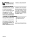
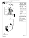
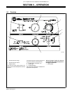
4-6. Connecting And Disconnecting Torch
Y Turn off power source and
disconnect input power.
1 Torch Connector
2 Quick Connect Collar
3 Nipple
4 Receptacle
5 Securing Pin
To connect torch:
Push torch connector onto
receptacle and quick connect until
collar secures nipple.
Rotate securing pin to lock
connector to unit.
To disconnect torch:
Rotate securing pin to unlock
connector from unit.
Push quick connect collar back
towards unit to release nipple, and
pull torch connector away from unit.
804 055-A
2
1
3
4
5