


. A complete Parts List is available at www.MillerWelds.com
OM-201 872 Page 17
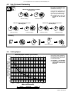
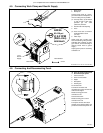
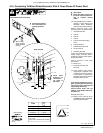
4-10. Connecting To Miller Welder/Generator With A Three-Phase AC Power Plant
Ref. 197 399 / 802 332-B
Three-Phase Generator Power
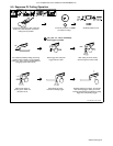
Y Stop engine.
Y Power and weld outputs are
live at the same time. Discon-
nect or insulate unused
cables.
. Have qualified person install ac-
cording to circuit diagram and
Generator Power Guidelines
(see generator Owner’s Manual).
Remove generator power panel
mounting screws. Tilt panel forward.
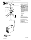
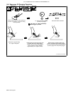
1 Circuit Breaker CB7
2 Lead 93
3 Lead 92
4 Lead 91
5 Lead 42 (Circuit Grounding
Lead)
6 Lead 90 (Neutral)
7 Isolated Neutral Terminal
8 Jumper Lead 42
9 Grounding Terminal
Jumper 42 is connected to lead 90 at
factory. Jumper 42 may be discon-
nected from neutral to meet applica-
ble electrical codes.
Lead 42 connects to front panel
Ground stud.
10 Power Cord
11 Circuit Breaker CB7 User
Terminals
. Circuit breaker CB7 protects
single-phase receptacle RC5
and the load wires from overload.
If CB7 opens, all three-phase
generator output stops and the
receptacle does not work.
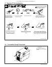
Connect user-supplied ring lug to
green (ground) lead. Connect ring
lug on end of green (ground) lead
to grounding terminal (9).
Connect black, white, and red
leads to circuit breaker CB7 user
terminals (11).
Reinstall power panel.
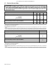
. Engine control must be set to
Run NOT Run/Idle to adequately
power the plasma cutter.
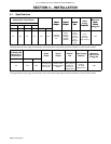
Tools Needed:
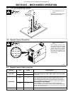
Volts
Amps
KVA/KW
Three
240
48
20
60 HzFrequency
Engine Speed 1850 RPM
AC
Phase
3
Output
Lead 42 connects to GROUND stud on
front of unit.
Jumper 42 is connected to 90 at factory.
91 92 93
240V
240V
3-Phase
2
3
4
5
6
7
8
9
10
11
Rear Of Panel
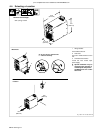
Three-Phase Power Connection
1
92
90
91
93
Y Close panel opening
if no connections are
made to generator.
Y Close panel
opening if no
connections
are made to
generator.
240V
Remove plug
before inserting
leads. Reinstall
bushing.
42
90