


. A complete Parts List is available at www.MillerWelds.com
OM-201 872 Page 16
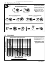
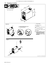
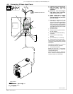
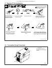
4-9. Connecting 3-Phase Input Power
803 766-A / 802 183
Y Installation must meet all National
and Local Codes − have only
qualified persons make this
installation.
Y Disconnect and lockout/tagout
input power before connecting
input conductors from unit.
Y Always connect green or green/
yellow conductor to supply
grounding terminal first, and never
to a line terminal.
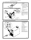
. The Auto-Line circuitry in this unit
automatically adapts the power
source to the primary voltage being
applied. Check input voltage available
at site. This unit can be connected to
any input power between 208 and 575
VAC without removing cover to relink
the power source.
1 Input Power Cord.
2 Disconnect Device (switch shown in
the OFF position)
3 Green Or Green/Yellow Grounding
Conductor
4 Disconnect Device Grounding
Terminal
5 Input Conductors (L1, L2 And L3)
6 Disconnect Device Line Terminals
Connect green or green/yellow grounding
conductor to disconnect device grounding
terminal first.
Connect input conductors L1, L2, and L3
to disconnect device line terminals.
7 Over-Current Protection
Select type and size of over-current
protection using Section 4-7 (fused dis-
connect switch shown).
Close and secure door on disconnect
device. Remove lockout/tagout device,
and place switch in the On position.
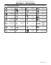
= GND/PE Earth Ground
L1
2
1
L2
L3
3
3
4
5
6
7
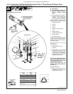
Tools Needed:
3/8 in
3/8 in