


. A complete Parts List is available at www.MillerWelds.com
OM-201 872 Page 24
SECTION 6 − MECHANIZED OPERATION
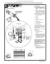
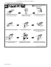
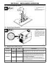
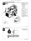
6-1. ICE-100TM Mounting Position
1 ICE-100TM Machine Torch
2 Square
Use a square to align torch perpen-
dicular to the work surface.
1
90°
2
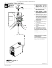
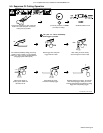
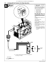
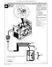
6-2. Remote Control Receptacle
804 026-A
1 Remote Control Receptacle
RC61
RC61 provides a remote arc start
input when using the ICE-100TM
machine torch. Connect supplied
remote control cable or remote
pendant control to receptacle on
rear panel. See Section 6-3 for
remote control cable input and
output functions.
1
21
5
3
476
9811 10
1214 13
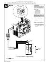
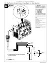
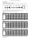
6-3. Remote Control Cable Functions
Function Lead Socket Lead Information
Remote Start
White 1 White and red leads connect to a set of customer-supplied remote contacts to
provide a remote trigger input signal to RC61 sockets 1 and 5 for the remote
Remote Start
Red 5
provide a remote trigger input signal to RC61 sockets 1 and 5 for the remote
start function.
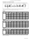
Okay To Move
Black 2 Black and green leads connect to a customer-supplied machine torch drive
device. Normally open contacts close after arc start to provide an output
signal to begin machine torch movement. These contacts can be either dry
(RMT1) or hot [RMT2 (+24 volts dc)] depending on plug position at RMT1 or
RMT2 receptacle on Control board PC1.
Okay To Move
Green 4
RMT2 receptacle on Control board PC1.
NOTE: The Spectrum 1251 is shipped from the factory with the plug
connected to RMT1 (dry contacts). To power a relay or isolated input module
with +24 volts dc on black lead (socket 2) and circuit common on green lead
(socket 4), see Section 6-4 or 6-5.
Noise Suppression Shielding 3 Chassis ground.