OM-1599 Page 11
SECTION 4 − INSTALLATION
4-1. Specifications
Type of
Input
Power
Welding
Power
Source
Type
Wire Feed
Speed
Range
Wire Type
And
Diameter
Input
Welding
Circuit
Rating
IP
Rating
Max. Wire
Spool
Capacity
Overall
Dimensions
Weight
Open-Circuit/
Arc Voltage,
15 − 100
Volts DC
Constant
Voltage (CV)
Or Constant
Current (CC)
DC
50 − 700 ipm
(1.3 − 18
mpm)
Depending On
Arc Voltage
Solid Steel:
.023 − .062 in
(0.6 − 1.6 mm);
Stainless Steel:
.023 − .052 in
(0.6 − 1.3 mm);
Flux Cored:
.030 − .052 in
(0.8 − 1.3 mm)
330 Amperes
At 60%
Duty Cycle
23
14 lb (6.4 kg),
8 in (203 mm)
Length: 15-5/8 in
(397 mm)
Width: 6-1/2 in
(165 mm)
Height: 14-1/2 in
(368 mm)
25 lb
(11 kg)
4-2. Gun Recommendation Table
Process Gun
GMAW − Hard or Corded Wires M25 Or M40
FCAW − Self-Shielding Wires FC-1260
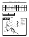
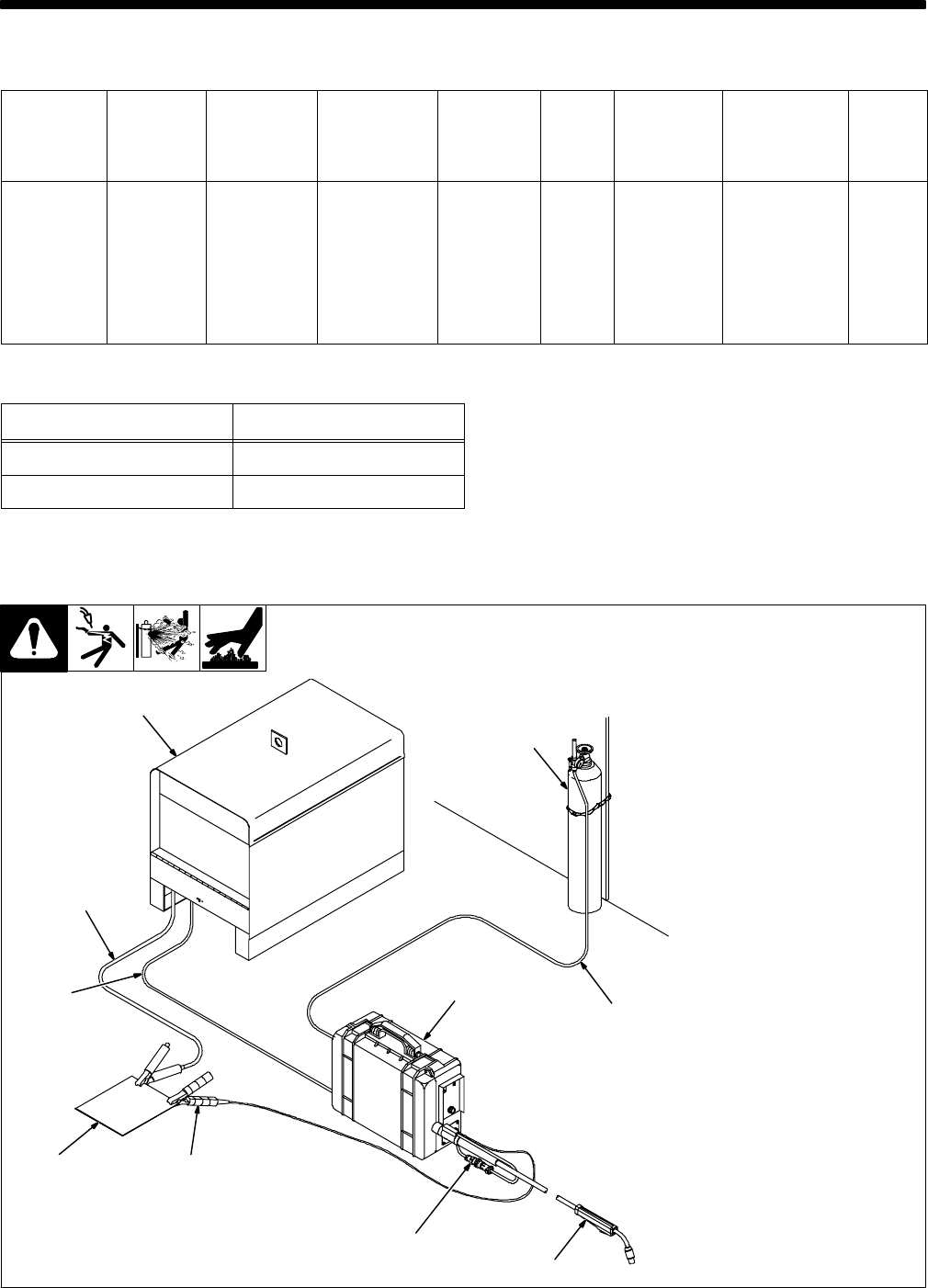
4-3. Equipment Connection Diagram
803 625-A
Y Turn Off wire feeder and
welding power source. Stop
engine on welding
generator.
1 Constant Current (CC) or
Constant Voltage (CV)
Welding Power Supply
2 Negative (−) Weld Cable
3 Positive (+) Weld Cable
4 Workpiece
5 Wire Feeder
6 Voltage Sensing Clamp
7 Gun
8 Gun Trigger Receptacle
9 Gas Hose
10 Gas Cylinder
1
2
3
4
5
9
10
7
8
6


