


OM-4407 Page 23
SECTION 6 − OPERATING WELDING GENERATOR
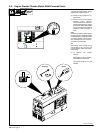
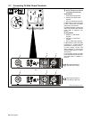
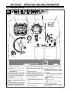
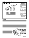
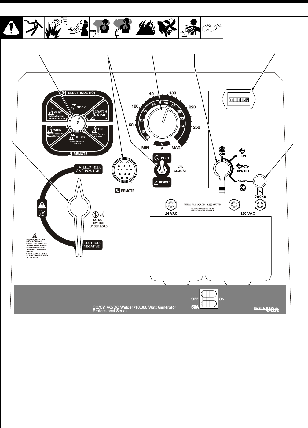
6-1. Front Panel Controls
1 Process/Contactor Switch
See Section 6-2 for Process/Contactor
switch information.
2 Voltage/Amperage Adjust Switch And
Remote Receptacle
Use switch to select front panel or remote
voltage/amperage control. For remote con-
trol, place switch in Remote position and
connect remote control to Remote recep-
tacle RC4 (see Sections 5-9 and 6-3).
3 A/V Control
Use control to select weld voltage or
amperage. Control may be adjusted while
welding.
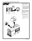
With Process/Contactor switch in any Stick
or TIG setting, use control to adjust amper-
age. With Process/Contactor switch in any
Wire position, use control to adjust voltage.
With V/A Adjust Switch in Remote position,
control limits the remote amperage in Stick
and TIG modes, but has no effect in MIG
modes.
4 Engine Control Switch
Use switch to start engine, select speed, and
stop engine. In Run/Idle position, engine
runs at idle speed at no load, and weld/power
speed under load. In Run position, engine
runs at weld/power speed.
. Place switch in Run position for TIG
(GTAW) welding using a high frequency
device.
. The unit will not return to idle speed
when the remote contactor is on.
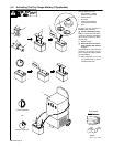
5 Engine Choke Control
Use control to change engine air-fuel mix
when starting engine.
To Start: pull out choke and turn Engine
Control switch to Start position. Release
switch and slowly push choke in when
engine starts.
. If the engine does not start, let the
engine come to a complete stop before
attempting restart.
To Stop: turn Engine Control switch to Off
position.
6 Engine Hour Meter
7 DC Polarity/AC Switch (AC/DC Models
Only)
Y Do not switch under load.
Use switch to select AC weld output or polar-
ity of DC weld output.
421
5
63
7
Ref. 206 422