


OM-4407 Page 26
SECTION 7 − OPERATING AUXILIARY EQUIPMENT
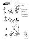
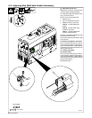
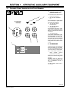
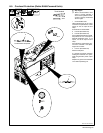
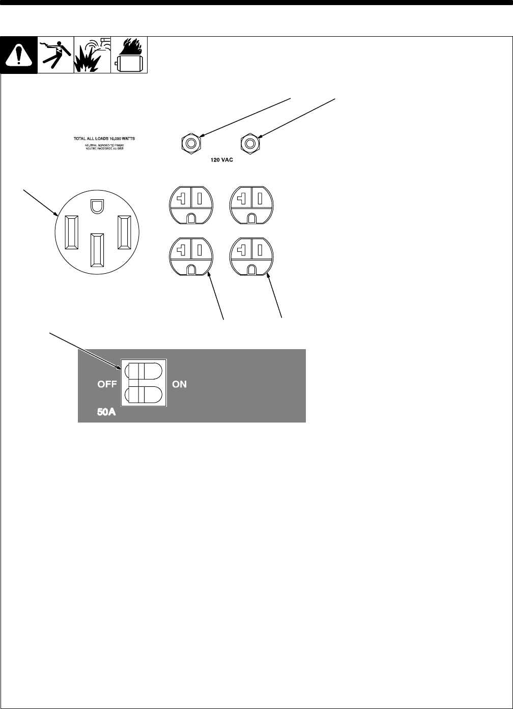
7-1. Generator Power Receptacles And Circuit Breakers
Ref. 206 422
1
2
5
3
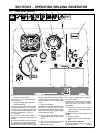
Y If unit does not have GFCI re-
ceptacles, use GFCI-
protected extension cord.
. Generator power decreases as
weld current increases.
1 240 V 50 A AC Receptacle
RC1
RC1 supplies 60 Hz single-phase
power at weld/power speed. Maxi-
mum output is 9.5 kVA/kW.
2 120 V 20 A AC Duplex
Receptacle RC2
3 120 V 20 A AC Duplex
Receptacle RC3
RC2 and RC3 supply 60 Hz single-
phase power at weld/power speed.
Maximum output from RC2 or RC3 is
2.4 kVA/kW.
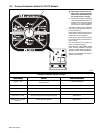
4 Circuit Breaker CB1
CB1 protects receptacles RC1, RC2,
RC3, and 115 volt ac output to Re-
mote Receptacle RC4 from over-
load. If CB1 opens, the receptacles
do not work and 115 volt ac output to
Remote Receptacle RC4 stops.
Place switch in On position to reset
breaker.
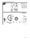
5 Circuit Breaker CB3
6 Circuit Breaker CB4
CB3 protects RC2 and CB4 protects
RC3 from overload. If a circuit break-
er opens, the receptacle does not
work. Press button to reset breaker.
. If circuit breaker continues to
open, contact Factory
Authorized Service Agent.
Combined output of all receptacles
limited to 10 kVA/kW rating of the
generator.
EXAMPLE: If 20 A is drawn from
each 120 V duplex receptacle, only
20 A is available at the 240 V
receptacle:
2 x (120 V x 20 A) + (240 V x 20 A) =
9.6 kVA/kW
6
4