


8 9
FEATURES
Miter system
The MILWAUKEE 6950-20 Miter Saw uses
a heavy duty steel plate with detents (stops).
This steel plate is extremely durable and pro-
vides for repeatable accuracy at each detent.
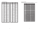
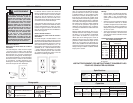
The miter angle can be set using detents
for commonly cut angles at 0°, 15°, 22.5°
31.62°, 45° Right and Left. The 6950-20
has a miter range from 52 left and right. An
industrial grade bearing allows the turntable
to be quickly and accurately adjusted to any
angle across the miter range.
Miter Angle Fine Adjust
In certain fi nish carpentry applications like
casing a window or door, it is necessary to
compensate for a non-square situation by
making a precision miter angle adjustment
to the turntable. The MILWAUKEE miter
angle fi ne adjust system makes this process
quick and easy, especially when the saw is
positioned near a miter detent (stop).
Digital Miter Angle Readout
The MILWAUKEE 6950-20 has a Digital Mi-
ter Angle Readout at the front of the turntable
that displays the miter angle of the turntable
to a resolution of 0.1°. The Digital Miter
Angle Readout is based on the mechanical
accuracy of the miter angle detent plate. It
calibrates itself each time the turntable is
placed in a miter detent and it requires no
adjustment.
Using the Miter Angle Fine Adjust in conjunc-
tion with the Digital Miter Angle Readout, it
is easy to make accurate minor angle ad-
justments anywhere along the miter range.
Using these systems together makes it easy
to re-position the turntable and repeat any
miter angle setting.
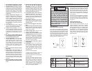
When the turntable is positioned at a LEFT
miter angle the digital readout will display
with a (-) symbol in front of the angle (for
example: -22.5° or -44.7°). When the turn-
table is positioned at a RIGHT miter angle
the digital readout will display as follows:
22.5° or 44.7°.
Dual Bevel Adjustment System
The Dual Bevel Adjustment System allows
for quick and accurate bevel adjustments
to either the Right or the Left. The bevel
angle can be set using detents (stops) for
the following commonly cut angles 0°, 22.5°,
33.85°, 45° Right and Left. The bevel mech-
anism also has several degrees of overtravel
beyond 45° on both the left and right.
Electronic Feedback Control Circuit
The Electronic Feedback Control Circuit
(EFCC) helps improve the operation and
life of the tool. It allows the tool to maintain
constant speed and torque between no-load
and load conditions. The soft start reduces
the amount of torque reaction at startup to
the tool and the user. It gradually increases
the motor speed up from zero to the top
no-load speed.
Electric Brake
The electric brake engages when the trig-
ger is released, causing the blade to stop
and allowing you to proceed with your work.
Generally the saw blade stops in four to fi ve
seconds. However, there may be a delay
between the time the trigger is released and
the time the brake engages. Occasionally
the brake may miss completely. If the brake
misses frequently, the saw needs servicing
by an authorized MILWAUKEE service sta-
tion. The brake is not a substitute for the
guards, so it is essential to always wait for
the blade to stop completely before removing
the blade from the kerf.
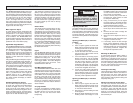
Lights
The MILWAUKEE 6950-20 Miter Saw has
two high power lights positioned on either
side of the blade to illuminate the workpiece
cutting area so that it is easy to see blade
approach the cutting line. An ON / OFF
switch for the lights is conveniently located
on the trigger handle. The bulb is designed
to provide several years of service. Uses
standard bulb size GE 193.
Dust Management System
The MILWAUKEE 6950-20 Miter Saw dust
collection system uses a large dust chute on
both sides of the blade to capture and direct
dust to back of the saw. The saw comes with
a Dust Elbow and a Dust Bag that attach to
the back of the Dust Chute. The dust bag
has a zipper located on the bottom of the
bag that makes it easy to empty. When using
the saw on a stand, the dust bag zipper can
be left open to allow the waste to fall into a
waste container.
Carrying Handles
For ease of transporting, multiple carrying
handles are provided, one on each side of
the table and one on top of the saw head.
Always lock the saw head down when
transporting.
WARNING
TOOL ASSEMBLY
To reduce the risk of injury, always
unplug tool before attaching or
removing accessories or making
adjustments. Use only specifi cally
recommended accessories. Others
may be hazardous.
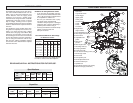
Adjusting the Miter Saw
The 6950-20 Miter Saw is fully adjusted at
the factory. If it is not accurate due to ship-
ping and handling, please follow these steps
to accurately set up your saw. Once the saw
is properly adjusted, it should remain accu-
rate under normal jobsite and transportation
conditions.
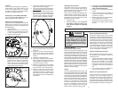
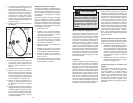
Squaring the Blade (90°) to the Fence
(0° Miter)
1. Unplug saw
2. Place a square against the fence and
blade and ensure that the square is not
touching blade teeth as this will cause
an inaccurate measurement.
3. Loosen the miter lock knob and move
the saw to the 0° miter position. Do not
tighten the lock knob.
4. If the saw blade is not exactly perpen-
dicular to the fence, use the supplied
wrench to loosen the screws that hold
the miter scale to the base. Move the
scale left or right until the blade is per-
pendicular to the fence. Use the square
to verify that the blade is perpendicular
to the fence. Retighten the screws.
5. Loosen the miter pointer adjustment
screw and reposition the pointer the so
that it indicates exactly zero. Once the
pointer is properly positioned, retighten
the miter pointer adjustment screw.
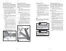
Squaring the Blade (90°) to the Table
(0° Bevel)
1. Unplug saw
2. Place a square against the table and
blade and ensure that the square is not
touching blade teeth as this will cause
an inaccurate measurement.
3. Remove the 6 screws holding the dust
chute together.
4. Move the bevel adjustment lever to the
middle position and wedge in a tool
(screw driver etc.) so the handle stay in
the middle position. Move the saw head
so that the bevel detent mechanism
locks into the 0° bevel detent.
5. Loosen 2 screws (T25) on the front of
the bevel arm, these screws are used
to clamp the detent body.
6. Using a T25 wrench you can adjust
the bevel setting of the blade-to-table.
Clockwise tilts blade to the right, coun-
terclockwise tilts blade to the left.
7. When you have the blade set to the 0°
bevel, torque the 2 screws to 85-100 in
lbs.
8. Remove the tool used to wedge the
bevel adjustment lever.
9. Move the bevel adjustment lever to
"lock".
10. Reassemble the dust chute sides, tight-
ening the 6 screws securely.
11. If necessary, loosen the left and right
bevel pointer adjustment screws and
reposition the pointers the so that they
indicates exactly zero. Once the pointers
are properly positioned, retighten the
bevel pointer adjustment screw.
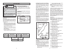
Mounting the Miter Saw
To prevent the tool from sliding, falling or
tipping during operation, the saw can be
mounted to a supporting surface such as a
level, sturdy work table or bench. Position the
saw and workbench to allow adequate room
for cross-cutting long workpieces. To mount
the saw, insert fasteners through the holes
in the corners of the saw base.
Installing the Dust Bag
Use the dust bag to collect or divert sawdust.
Insert the dust elbow into the dust chute on
the back of the saw. Then, attach the dust
bag by hooking it onto the dust elbow. Al-
ways empty the dust bag before storing and
frequently during use.
Raising and Lowering the Saw Head
The saw head must be locked down for
transporting and storing the tool. The tool
is shipped with the saw head locked down.
To unlock it, press and hold down the saw
head and simultaneously pull out the lock
down pin. To lock the saw head, press and
hold down the saw head and then push in
the lock down pin.