


10 11
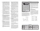
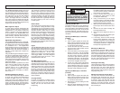
Lock-Off
There is a hole in the trigger through which a
padlock will fi t to lock the tool when it is not
in use. Use a padlock with a 1/4" shackle
and always unplug the tool before installing
it (padlock not supplied with tool).
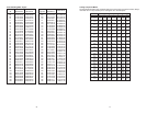
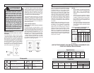
Selecting the Correct Miter Saw Blade
Use only miter saw blades with the
MILWAUKEE Dual Bevel Miter Saw.
Installing and Changing Blades
Always use clean, sharp blades because dull
blades tend to overload the tool, bind and
cause pinching. Use only 12" blades rated at
least 5500 RPM.
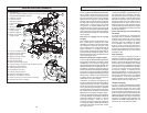
1. Unplug the tool.
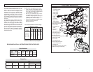
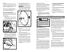
2. With the saw head up, use the wrench
to loosen the guard bracket rear screw
1/4 turn using the wrench provided (1).
3. Raise the lower guard (2).
Fig. 1
Loosen guard
bracket rear
screw
Rotate lower
guard up
1
2
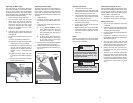
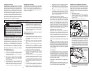
4. Loosen (do not remove) the guard
bracket front screw (3) until the guard
bracket can be raised to expose the
blade screw (4). Lower the lower guard
until it rests on the guard bracket front
screw. This will hold it up and out of the
way during the blade change.
Fig. 2
Loosen guard
bracket
front screw
3
4
Rotate guard
bracket up
5. Press in the spindle lock and rotate the
spindle until the lock engages.
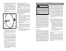
6. Use the wrench to loosen and remove the
left-hand thread blade screw clockwise.
7. Remove the outer blade fl ange, blade,
blade washer, and inner blade fl ange.
Wipe the fl anges, washer, and spindle
to remove dust and debris. Inspect the
parts for damage. Replace if needed.
Fig. 3
Outer fl ange
Inner fl ange
Blade
Blade
screw
Blade
washer
8. Install the inner blade fl ange as shown.
9. Insert the blade washer into the blade
arbor hole.
10. Match the arrow on the blade with the
arrow on the lower guard. Slide the
blade into the upper guard and onto the
spindle.
11. Install the outer blade fl ange.
12. Press in the spindle lock and rotate the
blade until the lock engages. Insert and
securely tighten the blade screw coun-
terclockwise with the wrench.
13. Rotate the guard bracket into position
and securely tighten the two screws. Re-
turn the wrench to the wrench holder.
14. Lower the saw head and check the
clearance between the blade and the
adjustable kerf plates. Important: The
lower guard must move freely. The blade
should rotate freely (see "Adjusting the
Kerf Plates").
Adjusting the Kerf Plates
Kerf plates reduce tear-out and splintering
along the cut by providing edge support.
Because blades vary in width, adjust the kerf
plates with every blade change.
Never make a cut without the adjustable kerf
plates installed. The kerf plates can be set
at their maximum width to accommodate all
blade widths and bevel angles if tear-out and
splintering are not a concern.
1. Unplug the tool.
2. Install the blade to be used. Each time
the blade is changed, check to be
sure the kerf plates are adjusted
properly.
Using Face Boards
(Zero Clearance Sub Fences)
There are face board mounting holes in the
fences for attaching face boards. Face boards
place distance between the fence and the
workpiece, providing improved support for
some workpieces. Workpiece splintering can
be reduced by using face boards. As the width
of the face board increases, the height of the
workpiece which can be cut increases slightly
(but the width capacity decreases slightly).
Similarly, if you place a face board on the saw
table and place a workpiece on top of the face
board, you can cut a workpiece with greater
width (but with less height).
Guards
The tool is shipped with both the upper and
lower guard installed. The lower guard should
cover the blade when the saw head is up and
it should move freely and open automatically
as the saw head is lowered into the workpiece.
If the lower guard appears loose, sticks, or if
it does not move to cover the blade when the
saw head is up, tighten the guard bracket
screws. If it still does not move freely, take
the saw to an authorized service center for
repairs. Do not attempt to open the guard
further than the automatic action permits.
WARNING
To reduce the risk of injury, wear
safety goggles or glasses with side
shields. Always wait for the blade
to stop completely and unplug the
tool before changing accessories or
making adjustments. Do not defeat
the guards.
OPERATION
Select the Workpiece Carefully
Be cautious of pitchy, knotty, wet or warped
workpieces. These materials are likely to cre-
ate pinching conditions. Workpieces that bow
and pinch may result in kick back. Inspect
for and remove nails before cutting. Always
keep blades clean and sharp; otherwise the
blade produces a narrow kerf and is likely
to be pinched by the workpiece. This tool is
not recommended for cutting ferrous metals
such as iron and steel. See Applications for
a more complete list of materials.
Support the Workpiece Properly
Always support the workpiece during opera-
tion. Otherwise, the workpiece may pull up
and into the saw.
1. Use the Fence: Align the workpiece fl ush
against the fence to provide a straight
path for the saw blade. This will help
eliminate the tendency for the blade
teeth to bind. The fence can be used as
a support for miter, bevel and compound
cuts.
2. Use a clamp: Clamp the workpiece to
the fence or base with a C-clamp.
Support of Longer Workpieces
Longer workpieces need support along their
full length. If you are using the saw on a
level work bench, prop up the workpiece to
a height of 4-3/4" from the bottom of the saw
feet. There are also many aftermarket work
tables specifi cally designed for miter saws that
provide supports for all types of workpieces.
3. Set the bevel angle. Each time the bevel
is changed, check to be sure the kerf
plates are adjusted properly.
4. Loosen the six kerf plate adjusting
screws.
5. Lower the saw head to the full depth of
cut (the point where the saw head will
not lower any further).
6. Slide the kerf plates to the desired spac-
ing and tighten the six screws.
7. Check to be sure the saw blade does not
contact the kerf plates before starting
the saw.