


1 Outline
1.3 Cautions on Creation of Fundamental Programs
18
FXCPU Structured Programming Manual
(Application Functions)
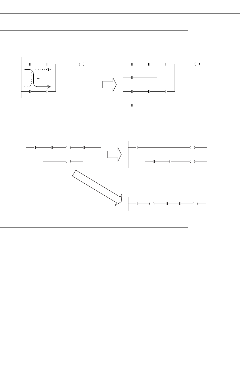
1.3.3 Circuits not available in structured ladder programs and countermeasures
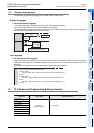
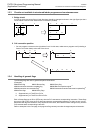
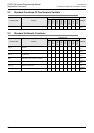
1. Bridge circuit
A circuit in which the current flows in both directions should be changed as shown in the right figure (so that a
circuit without D and a circuit without B are connected in parallel).
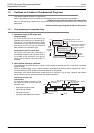
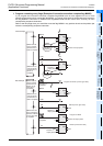
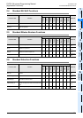
2. Coil connection position
• You can program a contact on the right side of a coil. In this case, make sure to program a coil (including a
function or function block) at the end of the circuit.
1.3.4 Handling of general flags
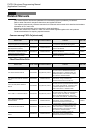
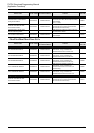
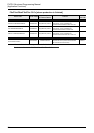
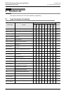
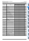
The following flags are valid in general sequence instructions:
(Examples)
M8020:Zero flag M8021:Borrow flag M8022:Carry flag
M8029:Instruction execution complete flag M8090:Block comparison signal
*1
M8328:Instruction non-execution flag
*1
M8329:Instruction execution abnormal complete flag
*2
M8304:Zero flag
*1
M8306:Carry flag
*1
*1. Supported only in FX3U/FX3UC PLCs.
*2. Supported only in FX
3U/FX3UC/FX3G PLCs.
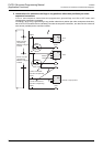
Each of these flags turns ON or OFF every time the PLC executes a corresponding instruction. These flags
do not turn ON or OFF when the PLC does not execute a corresponding instruction or when an error occurs.
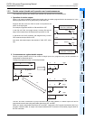
Because these flags are related to many sequence instructions, their ON/OFF status changes every time the
PLC executes each corresponding instruction.
Refer to examples in the next page, and program a flag contact just under the target sequence instruction.
A B
C
E
D
C E
A
B
A E
C
D
F F
Or
A B D A
B D
C
E
CE
AB
E
D
C