


Installation & Programming Manual FX & VFX “E” Series Inverte r/Charge r Sy ste m Copyright 2003 OutBack Power Systems, Inc.
19009 62
nd
Ave NE, Arlington WA 98223 USA
Page 10 Rev 7.0 07/02/04 Tel 360 435 6030 Fax 360 435 6019
MOUNTING
All OutBack FX’s can be mounted in any position. Better performance will be achieved if it is mounted in a location which allows for air
to circulate around the exterior of the casting. Locating the FX in a cool location will improve the operation and ensure the highest
efficiency and power capacity.
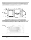
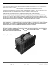
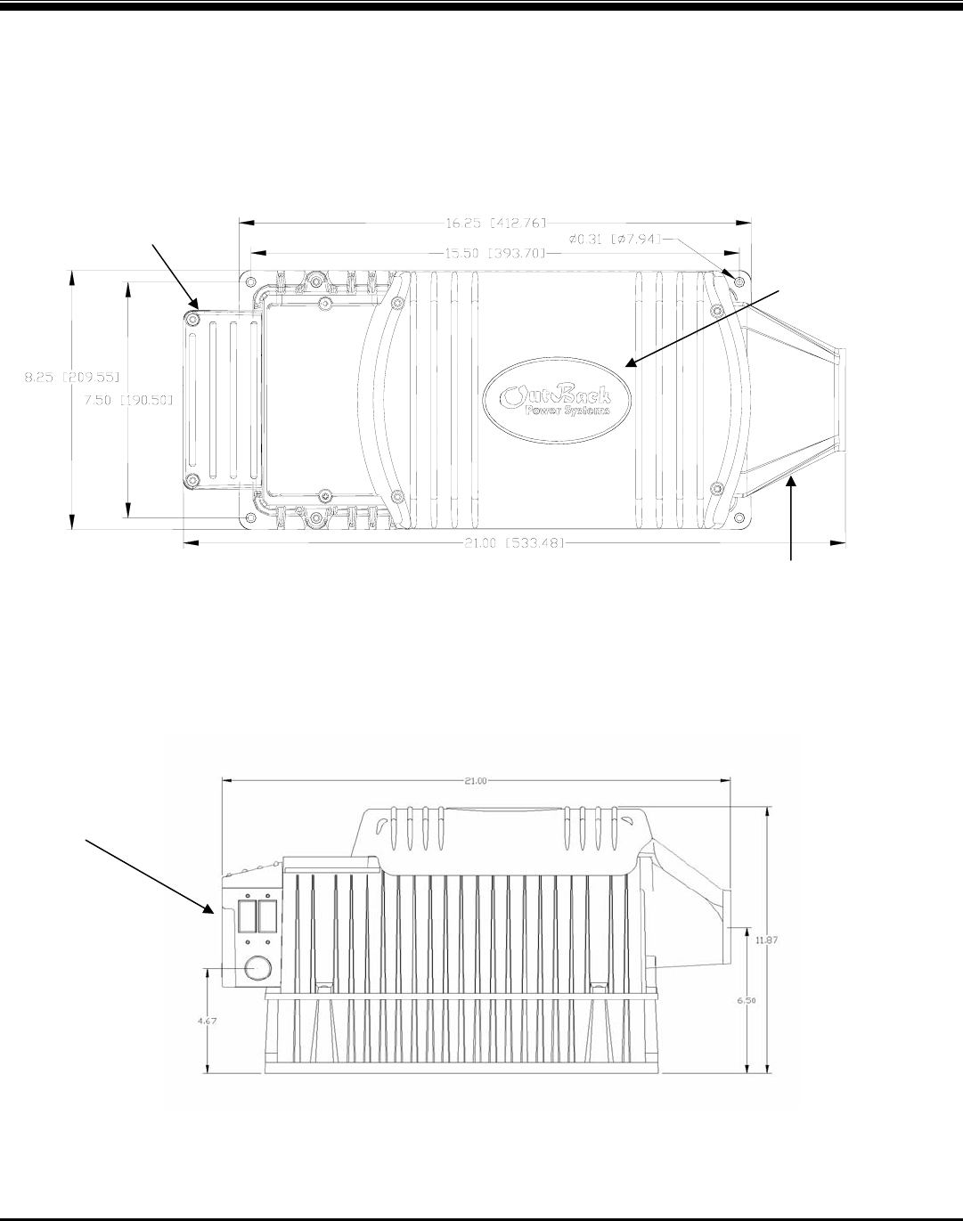
The following drawing provides the mounting and overall dimensions of the FX with the FXA kit (DCC + ACA + DCA) attached. The
first dimension is inches and the second value in parenthesis is the metric value in millimeters.
Depth out from Wall / Height up from Shelf: 11.87 inches (301 mm) / 12.87 INCHES (327mm) with Turbo installed
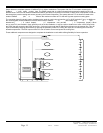
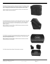
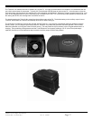
For installations where the FX may be exposed to water spray, either mount the FX with the base down (shelf mounting) or with the AC
wiring compartment at the bottom (wall mounting). This will minimize the entry of water into the AC wiring compartment.
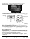
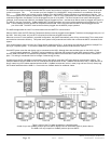
The FX-ACA can be used to add an AC outlet and one or two of OutBack’s AC rated OBDC circuit breakers (up to 70 amps max).
When these items are added to the FX, it should only be used in an area that is protected from rain.
Side view of FX with FXA kit attached. The Turbo Kit adds 1” (25mm) additional height to achieve a total height of 12.87” (327mm)
ACA
DCC
DCA
AC Outlet or
Circuit Breakers