


Copyright 2003 OutBack Power Systems, Inc. FX & VFX “E” Series Inverter/Charger System Installation & Programming Manual
19009 62
nd
Ave NE, Arlington WA 98223 USA
Tel 360 435 6030 Fax 360 435 6019 Rev 7.0 07/02/04
Page 13
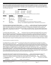
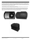
INDICATORS / CONTROL WIRING
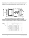
The AC wiring compartment also encloses the green terminal block used for the low voltage control wiring. This six position terminal
block can be unplugged to make wiring easier and to simplify the removal and reinstallation of an inverter. Two sets of multi-colored
LED indicators are provided to display the operation of the system. One set of three LED’s is provided to indicate the voltage level of
the battery connected to the DC terminals of the FX. This can be useful in troubleshooting the FX. These battery status LED’s operate
at the following voltage levels:
Nominal Battery Voltage
LED Color 12 VDC 24 VDC 48 VDC
Green 12.5 or higher 25.0 or higher 50.0 or higher
Yellow 11.5 to 12.5 23.0 to 25.0 46.0 to 50.0
Red 11.5 or lower 23.0 or lower 46.0 or lower
There is another set of three LED’s which indicates the operation of the FX. These LED’s are active as follows:
LED Color
LED Action LED Indicates
Green Solid GREEN Inverter ON
Flashing GREEN Search Mode or Slave Power Save
Off Inverter OFF
Yellow Solid YELLOW AC Source is Connected
Flashing YELLOW AC Input Live – Waiting to Connect to the FX
Off No AC Input Present
Red Solid RED Error – An Error Message will be automatically displayed on the MATE
Flashing RED Warning – A non-critical fault happened to the FX. The MATE can access this info.
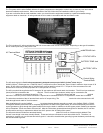
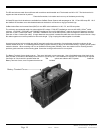
INVERTER ON/OFF
The left two terminals of the green terminal block marked INVERTER and ON/OFF can be used to control the inverter. Connecting the
two terminals together through a switch will allow control of the inverter output if a MATE is not available. A small jumper wire is pre-
installed into these two positions of the terminal block and needs to be removed in order to add the external switch. If the FX’s AC
output is off, check that the jumper wire is present and well connected. An installed switch overrides the control provided by the
OutBack MATE – if the switch is set to OFF, the MATE will not be able to turn ON the inverter. Cycling this switch quickly from ON to
OFF and then to ON again puts the inverter into Search mode. Cycling the switch in this fashion again returns the inverter to the ON
mode.
AUXILIARY OUTPUT ( AUX + / AUX - )
The Auxiliary output system uses the AUX + and AUX – terminals and is able to be programmed through the MATE to do a variety of
tasks. The default use for these terminals is to drive one 12-volt fan for external cooling. The power available at these terminals is 12
VDC at 0.7 amps (8.4 watts) maximum. These terminals should not be connected to any type of DC load which has a high inrush
current requirement. The FX includes internal electronic overcurrent protection for this 12 VDC output circuit which auto resets if it is
short circuited. No additional fuses are required. Use the OutBack FX Turbo Kit or DC12-FAN for cooling. For automatic or advanced
generator start functions, the Auxiliary Output can drive a 12V automotive relay for the 2-wire starting circuitry of a generator. OutBack
Power Systems does not support 3-wire start generators; however, a 3-wire to 2-wire conversion kit is available from a different source.
XCT + / XCT -
These terminals are not operational at this time.
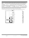
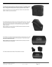
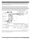
BATTERY TEMP {REMOTE TEMPERATURE SENSOR (RTS)}
The OutBack GFX has a 4 position “phone” RJ-11 modular jack located in the AC compartment for the connection of an optional
external battery temperature sensor, the RTS (sold separately), that allows for automatic adjustment of the battery charging process
based on the temperature of the battery. Battery manufacturers provide recommended charge voltages based on temperatures of 25C
/ 77F. With the RTS attached, the FX adjusts the battery voltage 0.03 volts per degree Celsius for a 12-volt battery bank, 0.06 volts per
degree Celsius for a 24-volt battery bank or 0.12 volts per degree Celsius for a 48-volt battery bank. When a HUB is used, the RTS
must be plugged into the Master FX which must be plugged into port 1 of the HUB. If this is the case, only one RTS is required for all
devices plugged into the HUB. The RTS should be stuck to the side of a battery below the electrolyte level so it can measure the
temperature of the batteries. The wire from the RTS can be folded and routed underneath the transparent gray plastic lexan cover of
the AC wiring compartment to allow connection to the battery. There is a small indentation in the aluminum casting to allow for the wire
to pass without affecting the sealing of the covers. When running additional wires under the smoked lexan cover, it may be required to
snip some lexan away to allow for wire routing. The lexan will not crack when cutting or filing.
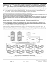
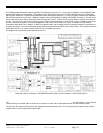
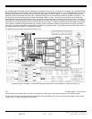
MATE / HUB
The 8 position “Ethernet” RJ-45 modular jack allows direct connection of a MATE system controller and display to the FX using
standard CAT5 type cabling. If multiple FX’s or an FX and an MX-60 charge controller are both in the system, an OutBack HUB
communication manager is be required for stacking of the FX’s and for efficient system performance. . The HUB acts similar to a
computer hub to combine the communication signals of the devices together into a networked system. OutBack offers two different
HUB products at this time. The HUB-4 accepts up to four OutBack products and one MATE. The HUB-10 connects up to ten OutBack
products and one MATE.
NOTE: Although the HUB has 2 ports for MATE’s only the 1
st
port is operational.