


29
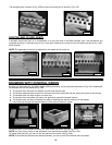
ANGLED JOINTS
OBTUSE ANGLED JOINTS
You can join boards at angles other than 90°. Four different methods are shown below by using the through dovetail
procedure.
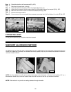
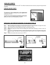
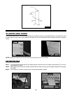
The simplest of these angled joints is the obtuse-angled
dovetail. In this joint, two boards are joined together at an
angle greater than 90°.
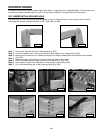
Fig. 50A
This joint can be made with either the template mounted to the
base of the jig or to a clamping board. If the angle is 100° or
greater, you must use the clamping board method.
Joint
Angle
SETUP WITH THE TEMPLA
TE MOUNTED TO THE BASE OF THE JIG
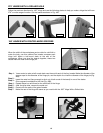
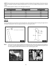
MAKE TWO COUNTERSINKS FOR
1/4-20 FLATHEAD SCREWS.
THE 1/4-20 SCREWS MUST NOT
PROTRUDE PAST THE OUTER
SURFACE OF THE INSERT.
"1
"12
"14
"9/16
"1-1/8
"1/4
DRILL TWO " HOLES1/4
INSERT ANGLE
Fig. 51A
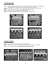
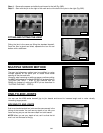
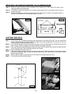
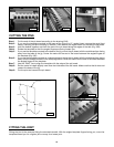
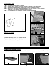
Make an angled insert according to one of the drawings (Figs. 51A and 51B).Match the angle of the insert
with the joint angle. If the workpiece is wider than 6" use the 12" insert.
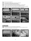
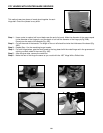
Make sure that the 1/4-20 flat-head screw does not protrude (A) Fig. 51C.
Remove the small front knobs, the front clamping rod, and the front clamping U channel. Leave the
springs.
Use two 1/2" 1/4-20 flat-head screws to secure the angled insert to the front of the base of the jig, with
the thicker edge of the insert up. If you are using the 6" insert, install it in the 2 holes on the right (Fig.
51C).
Replace the hardware that was removed in STEP 3.
Step 1 -
Step 2 -
Step 3 -
Step 4 -
Step 5 -
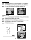
MAKE TWO COUNTERSINKS FOR
1/4-20 FLATHEAD SCREWS.
THE 1/4-20 SCREWS MUST NOT
PROTRUDE PAST THE OUTER
SURFACE OF THE INSERT.
"1"4
"7
"9/16
"1-1/8
"1/4
DRILL TWO " HOLES1/4
INSERT ANGLE
Fig. 51B
Fig. 51C
A