


36
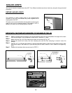
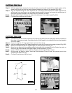
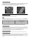
CUTTING THE PINS
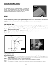
Cut the end of the tail board according to the drawing (Fig. 65A). Set the miter gauge and tilt the blade to
the values in the previous table. Remember that the miter gauge for the tailboard must be tilted opposite
for the pin board.
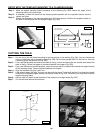
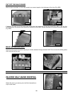
If you are using the 12" long angled insert, remove it from the jig.
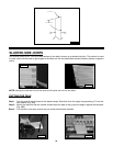
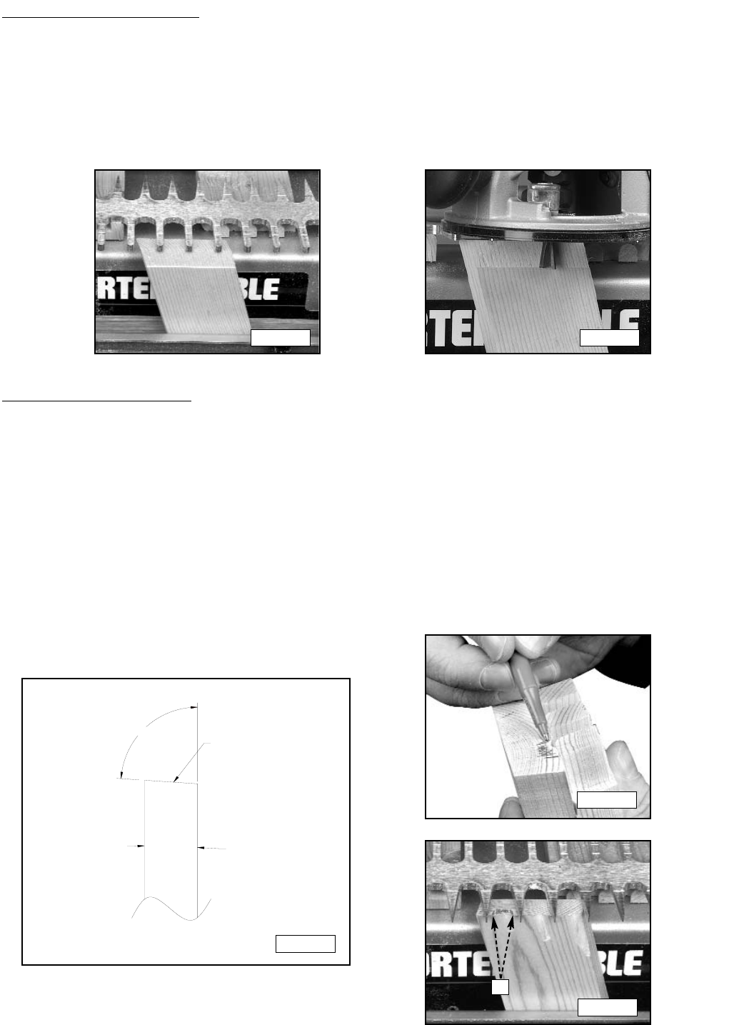
Hold the outside surfaces of the boards together and mark the pin board at the edges of the tail (Fig. 65B).
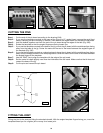
Rotate the template so that the angled fingers for cutting the pins is facing you.
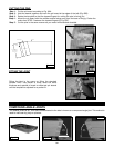
Mount the pin board with the outside surface facing away from the base of the jig. Center the marks on
the end of the board between the angled fingers of the template (A) Fig. 65C.
Use the "PINS" alignment line to align the template with the edge of the pin board.
Set the router bit depth to slightly more than the thickness of the tail board, but prevent the bit from
contacting the base of the jig..
Cut the pins and remove the pin board.
Step 1 -
Step 2 -
Step 3 -
Step 4 -
Step 5 -
Step 6 -
Step 7 -
Step 8 -
MAKE ANGLED CUT
OUTSIDE
SURFACE
OF BOARD
INSIDE
SURFACE
OF BOARD
BLADE TILT ANGLE
Fig. 65A
Fig. 65B
Fig. 65C
A
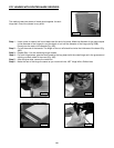
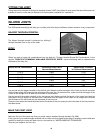
CUTTING THE TAILS
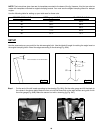
With the angled insert attached to the base of the jig, mount the tail board with the outside surface of the
board facing the jig and with the board centered between the fingers of the template (Fig. 64D).
Align the template using the “Tails” alignment line. If the angle is so steep that the “Tails” alignment line
will not work, you may have to use an angled clamping board. However, as long as the rounded part of
the fingers go past the edge of the wood, the set up will work fine as is.
Set the router bit depth to where the sides of the board go off at a slight angle (Fig. 64E).
Cut the tails and remove the tail board.
Step 2 -
Step 3 -
Step 4 -
Step 5 -
Fig. 64D Fig. 64E