


30
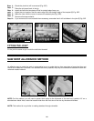
Fig. 53C
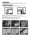
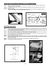
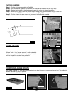
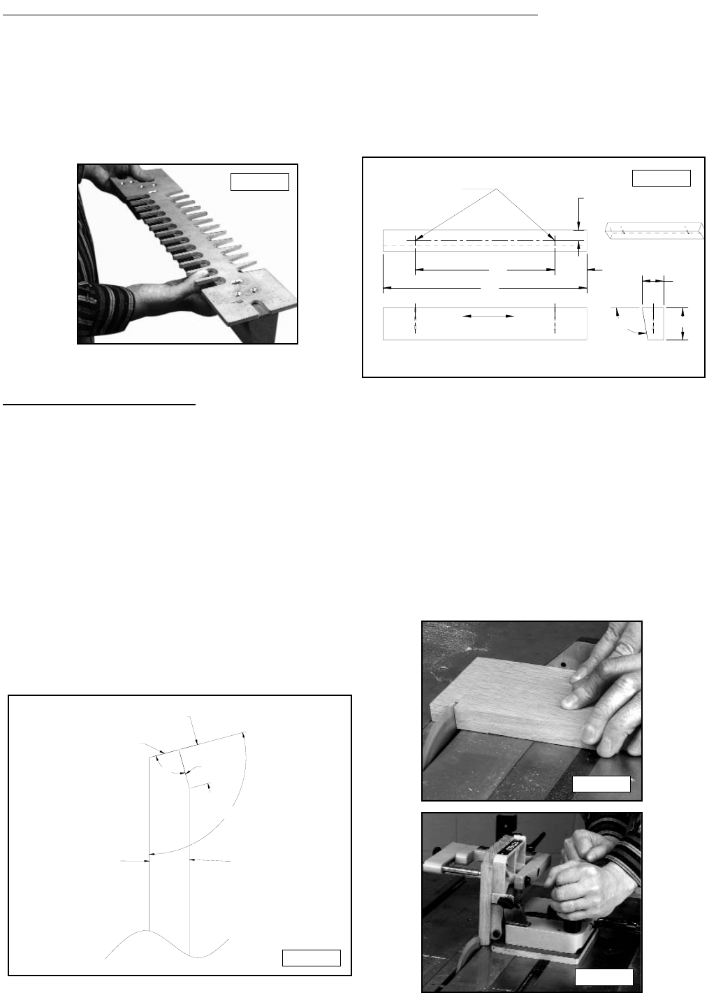
Cut the end of the tail board according to the instructions in the drawing (Fig. 53A). You can make these
cuts on a table saw with the blade beveled (Fig. 53B). Set the miter gauge at 90° for the first cut, then use
a tenoning jig for the second cut (Fig. 53C).
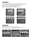
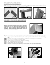
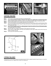
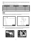
If you use the template mounted to the base of the jig, mount the board with the outside face toward the
base of the jig. Center the edges of the board between two fingers (Fig. 53D).
If you use the board-mounted template, clamp the board with the outside face toward the angled surface
of the clamping board. Center the board between two fingers.
Align the template using the “tails” line.
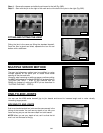
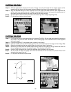
If the angle is steep, the “tails” line may not align with the wood. The joint will be fine if you place the straight
portion of the template fingers directly over the tail board (A) Fig. 53E. Otherwise, you may have to use an
angled clamping board.
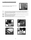
Set the router bit depth where the sides of the board are at a slight angle (Fig. 53F).
Cut the tails and remove the tail board.
Step 1 -
Step 2 -
Step 3 -
Step 4 -
Step 5 -
Step 6 -
Step 7-
CUTTING THE TAILS
OUTSIDE
SURFACE
OF BOARD
FIRST CUT
SECOND CUT
INSIDE
SURFACE
OF BOARD
90°
ANGLE BETWEEN BOARDS
THICKNESS OF PIN BOARD
Fig. 53A
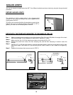
WOOD GRAIN
DRILL PILOT HOLES
FOR #10 WOOD SCREWS
"13 "3
"1
"19
"2
"3
ANGLE OF
BOARDS
Fig. 52B
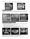
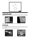
SETUP WITH THE TEMPLATE MOUNTED TO A CLAMPING BOARD
Fig. 52A
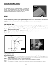
Make an angled clamping board according to the drawing (Fig. 52B). Match the angle of the
clamping board to the joint angle.
If necessary, create flat places on the clamping board parallel with the opposite side so that the
clamps can grab.
Attach the template to the clamping board with #10 wood screws. Position the angled surface on
the side of the template with the straight fingers (Fig. 52A).
Step 1 -
Step 2 -
Step 3 -
Fig. 53B