


9
Step 3 -
Step 1 -
Step 2 -
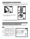
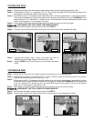
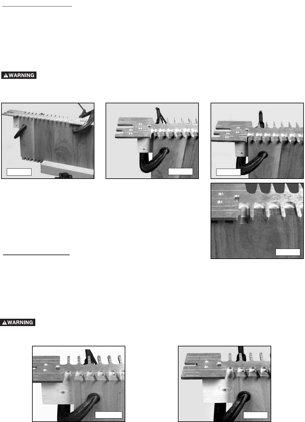
CUTTING THE TAILS
Fig. 10B
Fig.10A
Step 5 -
Step 4 -
Fig. 10C
Step 6 -
Step 7 -
Step 8 -
Fig. 10D
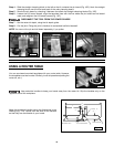
Clamp the tail board with the outside surface facing away from the clamping board (Fig. 10A).
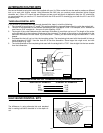
If the board is a width in 1" increments, (12", 13", etc.), center the edge of the board exactly between the
two fingers of the template farthest to the left (Fig. 10B).
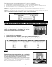
If the board is not in 1" increments, take the fraction of an inch that is greater than 1" and divide it by two.
Then move the tailboard to the left of the center of the fingers by that amount (Fig. 10C). EXAMPLE: IF the
board width is 16-1/2", take the 1/2", divide it by two. You would then move the tail board to the left of the
center of the fingers by 1/4" and clamp it in place.
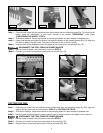
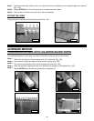
Use a piece of wood the same thickness as the pin board to mark the router bit depth.
DISCONNECT THE TOOL FROM THE POWER SOURCE.
Set the router bit depth, using the pencil mark from STEP 4.
Connect your router to the power source and cut the pins as far as the template will allow.
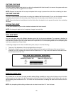
Unclamp the templet, slide it down, and center the last cut
between the two straight fingers and reclamp (Fig. 10D).
Repeat STEPS 6 and 7 until the pins are cut across the entire
board.
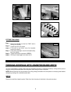
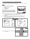
Clamp the pin board with the outside surface facing away from the clamping board.
If the board is a width in 1" increments, (12", 13", etc.), center the edge of the board exactly in line with the
finger of the template farthest to the left (Fig. 11A).
If the board is not in 1" increments, take the fraction of an inch that is greater than 1" and divide it by two.
Then move the pin board to the left of center of the fingers by that amount. EXAMPLE: IF the board width
is 16-1/2", take the 1/2", divide it by two. You would then move the tail board to the left of the leftmost
finger by 1/4" and clamp it in place (Fig. 11B).
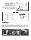
Use a piece of wood the same thickness as the pin board to mark the router bit depth.
DISCONNECT THE TOOL FROM THE POWER SOURCE.
Set the router bit depth, using the pencil mark from STEP 4.
Connect your router to the power source and cut the pins as far as the template will allow.
CUTTING THE PINS
Step 3 -
Step 1 -
Step 2 -
Step 5 -
Step 4 -
Step 6 -
Fig. 11A
Fig. 11B