


31
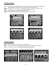
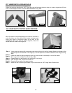
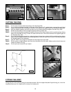
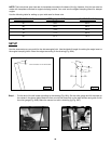
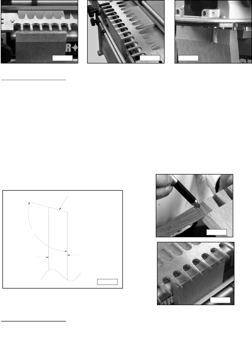
Fig. 53D
Fig. 53E
Fig. 53F
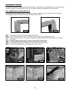
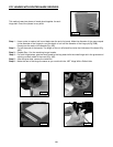
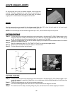
CUTTING THE PINS
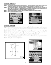
Cut the end of the pin board according to the drawing (54A).
If you use the template mounted to the base of the jig and a 12" angled insert, remove the small front
knobs, clamping rod and clamping U channel. Then remove the angled insert and reinstall the hardware.
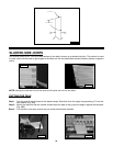
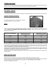
Hold the boards together and mark the end of the pin board along the edges of the tails (Fig. 54B).
Rotate the template so that the angled fingers are facing toward you.
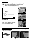
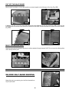
If you use the template mounted to the base of the jig, mount the pin board with the outside surface facing
away from the base of the jig. Center the marks on the end of the board between the angled fingers of
the template (Fig. 54C).
If you use the template mounted on a clamping board, clamp the pin board with the outside surface facing
away from the straight surface of the clamping board. Center the marks on the end of the board between
the angled fingers of the template.
Use the "PINS” line to align the template with the edge of the pin board.
Set the router bit depth slightly more than the thickness of the tail board. Make sure that the bit does not
contact the base of the jig.
Cut the pins and remove the pin board.
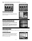
Step 1 -
Step 2 -
Step 3 -
Step 4 -
Step 5 -
Step 6 -
Step 7-
Step 8-
Step 9-
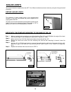
OUTSIDE
SURFACE
OF BOARD
INSIDE
SURFACE
OF BOARD
MAKE ANGLED CUT
A
NGLE BETWEEN BOARDS
Fig. 54A
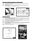
Fig. 54B
Fig. 54C
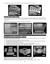
FITTING THE JOINT
Fitting the joint is the same as fitting the standard dovetail. With the angled template fingers facing you, move the
template toward you for a tighter joint or away for a looser joint.