


7
Fig. 6B
Fig. 6C Fig. 6D
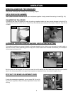
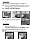
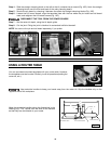
CUTTING THE TAILS
Step 3 -
Step 1 -
Step 2 -
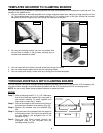
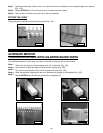
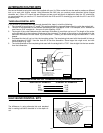
Clamp the tail board with the outside surface facing away from the clamping board (Fig. 7A). Align the tail
board, using the instructions in your basic manual in the section “OPERATION”. Look under
“POSITIONING THE WOOD”, STEP 4.
This step is optional. Clamp stop blocks to the clamping board for rapid setups of repeated cuts.
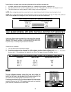
Use a small square and a pencil to draw a line along the bottom of the clamping board (Fig. 7B). Align the
line with an edge of the tail board. (This line will be used to set up the pin board).
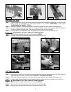
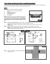
Use the width of the pinboard to mark the depth of the router bit on the tailboard (Fig. 7C).
DISCONNECT THE TOOL FROM THE POWER SOURCE.
Set the router bit depth, using the pencil mark from STEP 4.
Connect your router to the power source and cut the tails (Fig. 7D).
Step 4 -
Step 5 -
Step 6 -
Fig. 7A
Fig. 7B
Fig. 7C
Fig. 7D
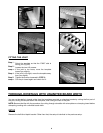
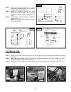
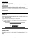
CUTTING THE PINS
Step 3 -
Step 1 -
Step 2 -
Clamp the pin board with the outside surface facing away from the clamping board (Fig. 8A). Align the
edge of the pin board with the line drawn in STEP 3 of “CUTTING THE TAILS”.
This step is optional. Clamp stop blocks to the clamping board for rapid setups of repeated cuts.
Use the width of the tail board to make a pencil mark on the pin board for the depth of the router bit.
DISCONNECT THE TOOL FROM THE POWER SOURCE.
Set the router bit depth, using the pencil mark from STEP 3.
Connect your router to the power source and cut the pins (Fig. 8C).
Remove the pin board and check the fit with the tail board (Fig. 8D).
Step 4 -
Step 5 -
Step 6 -