


14
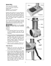
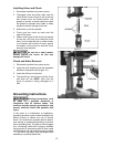
6. Make sure the coil spring cover is pushed
back in, then tighten the two hex nuts (D).
Do not over tighten. The hex nuts should be
tightened against each other.
7. Re-install hub, washers, hex nut and cap.
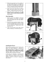
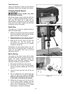
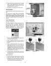
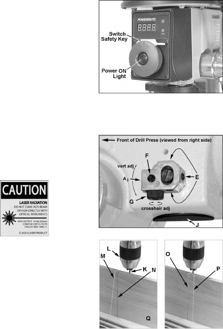
On/Off Switch
Pull out the switch to start the drill press, push to
stop.
The switch has a safety feature that prevents
unauthorized or accidental starting of the drill
press. With the switch in the "off" position, slide
out the switch safety key (Figure 20). This piece
must be re-inserted before the drill press can
operate.
Laser Adjustment
(Figures 21 through 23)
The Laser Assembly has been installed and pre-
set at the factory. It should, however, be
checked and any adjustments made before
operating the drill press. It should also be re-
checked periodically, as constant machine
vibration may cause it to become misaligned.
1. Remove the guards (item 184, page 18) to
access the laser assemblies.
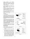
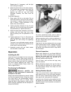
2. Take a length of board (Q) and draw a
perpendicular line (N) on one side using a
square.
3. Place a small drill bit (K) in the chuck (L),
then place the board (Q) on the table on
edge against the drill bit with the marked-
line side toward the back of the drill press.
Important: The table should be in horizontal
position and locked. Verify that the line (N)
is perpendicular to the table.
4. Connect power to the drill press, and turn on
the laser using the button at the front of the
drill press head.
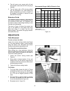
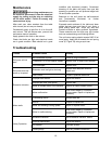
Vertical Alignment
5. Manually rotate the laser assembly (A
2
) and
move the board from side to side as
required until the laser light (M) lines up with
the board marking (N) to look like (O). Then
carefully tighten the three setscrews (E).
Figure 20
Figure 21
Figure 22