


9
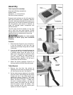
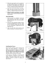
3. Slide the large handle onto the spindle of
the table bracket (Figure 4), and tighten the
set screw in the handle with a 3mm hex
wrench. Crank the handle counterclockwise
to lower the table bracket down the column.
4. Place the ring onto the column and slide it
down over the top edge of the rack (see
Figure 3). Tighten the set screw on the ring.
5. Screw the locking handle into the table
bracket (Figure 4) and tighten the locking
handle to secure the table bracket’s position
on the column.
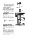
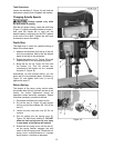
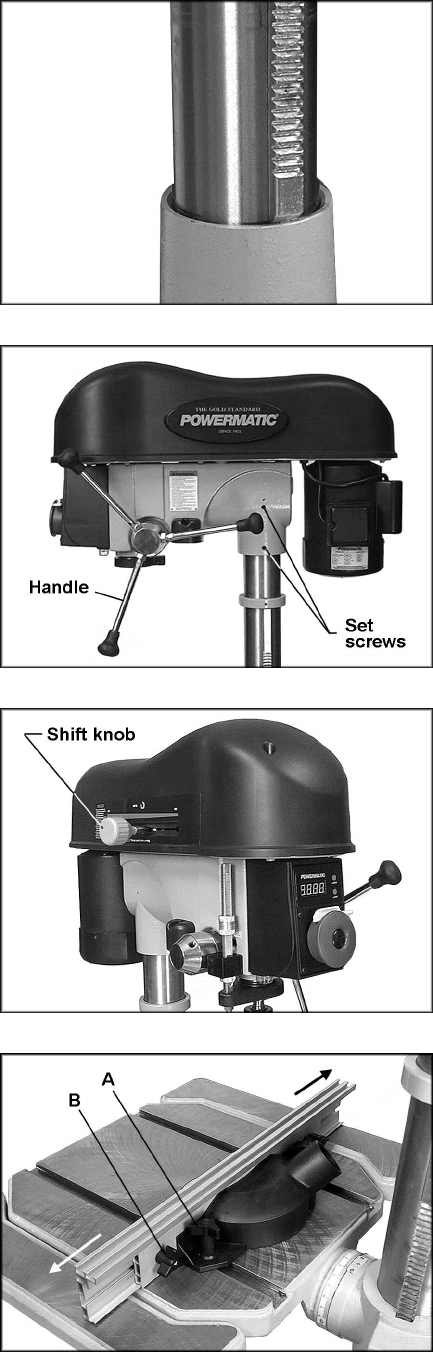
Head Assembly
1. With the help of an assistant, mount the
head assembly to the column, and tighten
the two set screws with a 5mm hex wrench.
See Figure 6.
2. Screw the three downfeed handles (Figure
6) into the threaded holes in the hub. These
can be mounted to either side of the head
for your convenience. Tighten the hex nuts
against the hub.
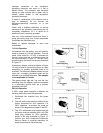
3. Insert the shift knob into the collar on the
side by screwing it in clockwise (Figure 7).
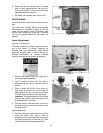
Installing the Fence
Slide the fence assembly into the T-slots on the
table. The fence assembly is secured by
tightening the knobs (A, Figure 8). The fence
can be expanded by loosening the smaller
knobs (B, Figure 8) and sliding the fence halves
outward. Tighten all four knobs on the fence
assembly before operating the drill press.
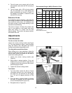
A dust chute (2” diameter) is mounted to the
fence assembly for attaching a dust collection
system. The fence halves must be in the
expanded position to provide an opening for
dust exhaust.
Figure 5
Figure 6
Figure 7
Figure 8