


13
Adjustments
Disconnect machine from
power source before making adjustments.
Failure to comply may cause serious injury.
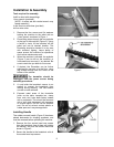
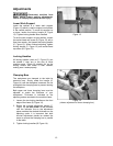
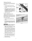
Lower Work Support
Inside the cabinet is a lower work support
(Figure 13) which is used to support work pieces
in the vertical position. To move this support up
or down, loosen the locking handle (A, Figure
13). Tighten locking handle when finished.
To set the work support at level position, loosen
the socket head cap screw (B, Figure 13) with a
6mm hex wrench, and loosen the locking handle
(C, Figure 13). When finished adjusting, tighten
locking handle (C, Figure 13) and socket head
cap screw (B, Figure 13).
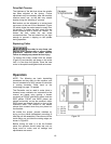
Locking Handles
All locking handles (such as C, Figure 13) can
be rotated if they are in the way of other
machine parts. Simply lift straight out on the
locking handle and rotate it, then release,
making sure it seats properly.
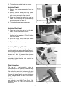
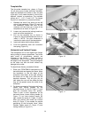
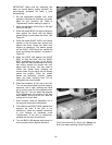
Clamping Bars
The workpieces are clamped to the table by
eccentric bars. Simply rotate the handle (A,
Figure 14) until the workpiece is secured. Do not
overtighten the clamping bars to prevent denting
the workpiece.
Both upper and lower clamping bars must be
adjusted to match the thickness of your
workpieces. Thickness is indicated on the
adjoining scales mounted to the machine frame.
1. Loosen the two locking handles on the front
edge of the frame (B, Figure 14).
2. Rotate the knurled adjustment pieces (C,
Figure 14) on both sides of the machine
until the indicator line on the adjustment
piece matches the desired thickness on the
adjoining scale. It is important that both
knurled adjustment pieces be rotated the
same to ensure the clamping bar is parallel
to the table.
3. Tighten locking handles (B, Figure 14).
Figure 13
Figure 14
(shows adjustment of lower clamping bar)