


14
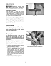
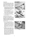
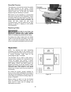
Template Bar
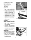
The four-sided template bar, shown in Figure
16, will allow you to create “half-blind” dovetails,
where the dovetails are visible on only one side
of the joint. It will create dovetails in one of four
different “pitches” or centerlines. The available
pitches are 1”, 1-1/2”, 2” and 2-1/2”. To change
the pitch of a dovetail cut, proceed as follows:
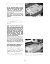
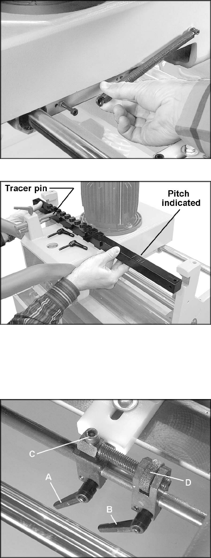
1. Release one end of the spring on the left
side of the headstock (Figure 15) and pull
the headstock toward the front of the
machine until the tracer pin is clear of the
template bar as shown in Figure 16.
2. Loosen and remove the locking handle on
each end of the template bar.
3. Pull out the template bar as shown in
Figure 16, flip it to the desired side, then re-
install it. NOTE: The pitch dimension is
inscribed on each side of the template bar.
4. Insert and tighten both locking handles.
5. Push the headstock back and re-connect
the spring (Figure 15).
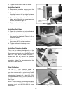
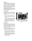
Horizontal and Vertical Fences
The workpieces will lie flush against the fences
during cutting to ensure squareness. Two buffer
pads made of polyethylene material are
mounted to the fences – these provide a
“chipbreaker” effect to prevent chip-out on the
left edges of the workpieces. They are designed
so the cutter can bite into them without any
damage to the cutter.
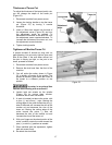
To adjust these fences, proceed as follows:
1. Place your FRONT/BACK workpiece on the
horizontal table and against the fence. Move
the headstock to the left edge of the
workpiece, then slide it to the right, allowing
the tracer pin to slide just a little into the
template recesses. This will give you an
idea where the cuts will be made and how
they will be spaced across the width of the
workpiece.
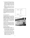
2. For broad movement of the horizontal fence,
loosen both locking handles on the
horizontal fence (A and B, Figure 17) and
slide the horizontal fence into position.
There is also a micro adjustment on the
horizontal fence; loosen locking handle (A,
Figure 17), but leave locking handle (B)
tight. Loosen the screw (C, Figure 17) with a
6mm hex wrench and rotate the knurled
knob (D, Figure 17) as needed for precise
positioning of the horizontal fence. When
finished, tighten screw (C, Figure 17) and
locking handle (A, Figure 17).
Figure 15
Figure 16
Figure 17