


13
2. Remove the top left side panel so that you
can rotate the cutterhead using the belts.
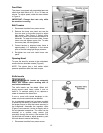
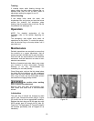
3. To remove a knife insert, unscrew the flat
head screw with a spline screwdriver, or the
air-operated screwdriver using one of the
provided T-20 spline bits. If the screw will
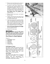
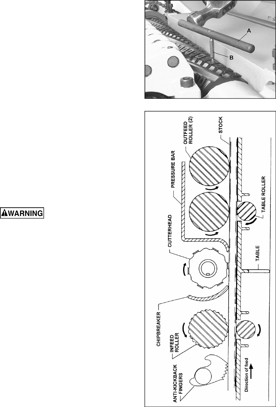
not budge, place the hole of the breaker rod
(A, Figure 7) over a spline bit (B, Figure 7)
and lightly tap the breaker rod
counterclockwise with a hammer to break
loose the screw.
4. Remove the flat head screw, and remove
the knife insert.
5. Carefully wipe clean the insert seat on the
cutterhead and install the new knife insert
(or rotate the present one).
6. The knife insert should be “pre-set” and then
given a final tightening. Install the flat head
screw, and turn the screw until the knife
insert is snug. To pre-set, you may use one
of the spline screwdrivers provided, or use
the air-operated screwdriver set at 45 psi.
7. When finished pre-setting the knife insert,
set the air operated screwdriver to 85 psi,
and fully tighten the screw.
8. Repeat for all knife inserts.
Make sure all knife inserts
are secure in the cutterhead. Failure to
comply may allow knife inserts to loosen and
be flung from the machine during operation.
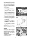
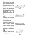
The Planer’s Feed System
(Figure 8)
1. Anti-Kickback Fingers
2. Infeed Roller
3. Chipbreaker
4. Cutterhead
5. Pressure Bar
6. Outfeed Rollers
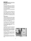
Anti-Kickback Fingers
Anti-kickback fingers help prevent stock from
being thrown from the machine. These fingers
operate by gravity and should be inspected for
pitch or gum buildup before each day’s use. The
fingers must operate freely and move
independently for correct operation.
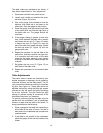
Infeed Roller
The function of the infeed roller is to feed the
material into the machine. It is a corrugated,
sectional roller with approximately 1/4”
independent movement of each section to
accomodate multiple board surfacing.
Figure 7
Figure 8