


14
To provide proper drive, the infeed roller should
be set so that the bottom of its arc is 1/16” below
the arc of the cutterhead knife inserts. The
infeed roller is under spring tension and this
tension must be sufficient to feed the stock
uniformly through the planer without slipping but
should not be so tight that it causes damage to
the boards. The tension should be equal at both
ends of the roller.
To adjust the infeed roller:
1. Disconnect machine from power source.
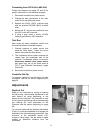
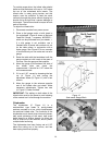
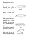
2. Place a dial gauge under a knife insert in
the cutterhead. (Figure 9 shows a Bed and
Feed Roll Gauge – accessory #2230002 –
which can be purchased from your dealer. )
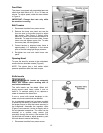
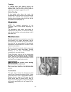
If a dial gauge is not available, use a
finished block of wood with notches cut out
for the table rollers, in conjunction with a
feeler gauge. See Figure 10 for an example
of a wood block you can make and use as a
gauge.
3. Raise the table with the handwheel until the
gauge contacts a knife insert at the apex of
its curve. Zero the gauge at that position.
4. Move the gauge to the extreme left side of
the infeed roller and check the
measurement. It should be 1/16” below the
knife measurement.
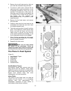
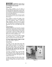
5. If it is not 1/16”, correct by loosening the hex
nut (A, Figure 11) and turning the
adjustment screw (B, Figure 11) with a hex
wrench.
6. Move the gauge to the extreme opposite
end of the infeed roller and check. Make
necessary adjustments. Tighten hex nuts
(A, Figure 11) when finished.
IMPORTANT: The setting on both sides of the
infeed roller must be the same to avoid skewing
of the material as it is fed through the machine.
Chipbreaker
The chipbreaker (C, Figure 11) is a
sectionalized type made of spring-loaded
sections mounted on a bar, which complements
the sectional infeed roller. The functions of the
chipbreaker are to break chips into small pieces,
help avoid splintering of the wood, help avoid
board bounce on thinner boards, to direct the
flow of chips out of the machine, and to permit
multiple board surfacing.
The chipbreaker has been factory set at 1/32”
below the cutting arc of the knives, and has
been spring-tensioned properly.
Figure 9
Figure 10
User-made Gauge Block
Figure 11