


16
ASSEMBLY
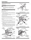
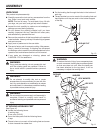
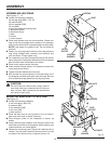
ASSEMBLING LEG STAND
See Figures 11 - 12.
n Locate the following hardware:
40 carriage bolts (M8 x 1.25-16)
40 washers (M8)
40 lock washers (M8)
40 nuts (M8)
4 legs (with attached leveling feet)
2 leg braces (short)
2 leg braces (long)
1 base
2 screws
1 motor support
n Place base upside down on a level surface. Fasten four
legs to top using carriage bolts, washers, lock washers,
and nuts, as shown (with nuts and washers to the inside).
NOTE: Legs fasten to outside of top. Do not tighten at
this time.
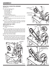
n Fasten two long leg braces and two short leg braces to
legs using carriage bolts, washers, lock washers, and
nuts, as shown. Finger tighten only.
n Turn assembly over onto the legs. Be sure all four feet sit
flat on the ground. Adjustment of the feet will be completed
after the band saw is attached to the stand.
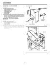
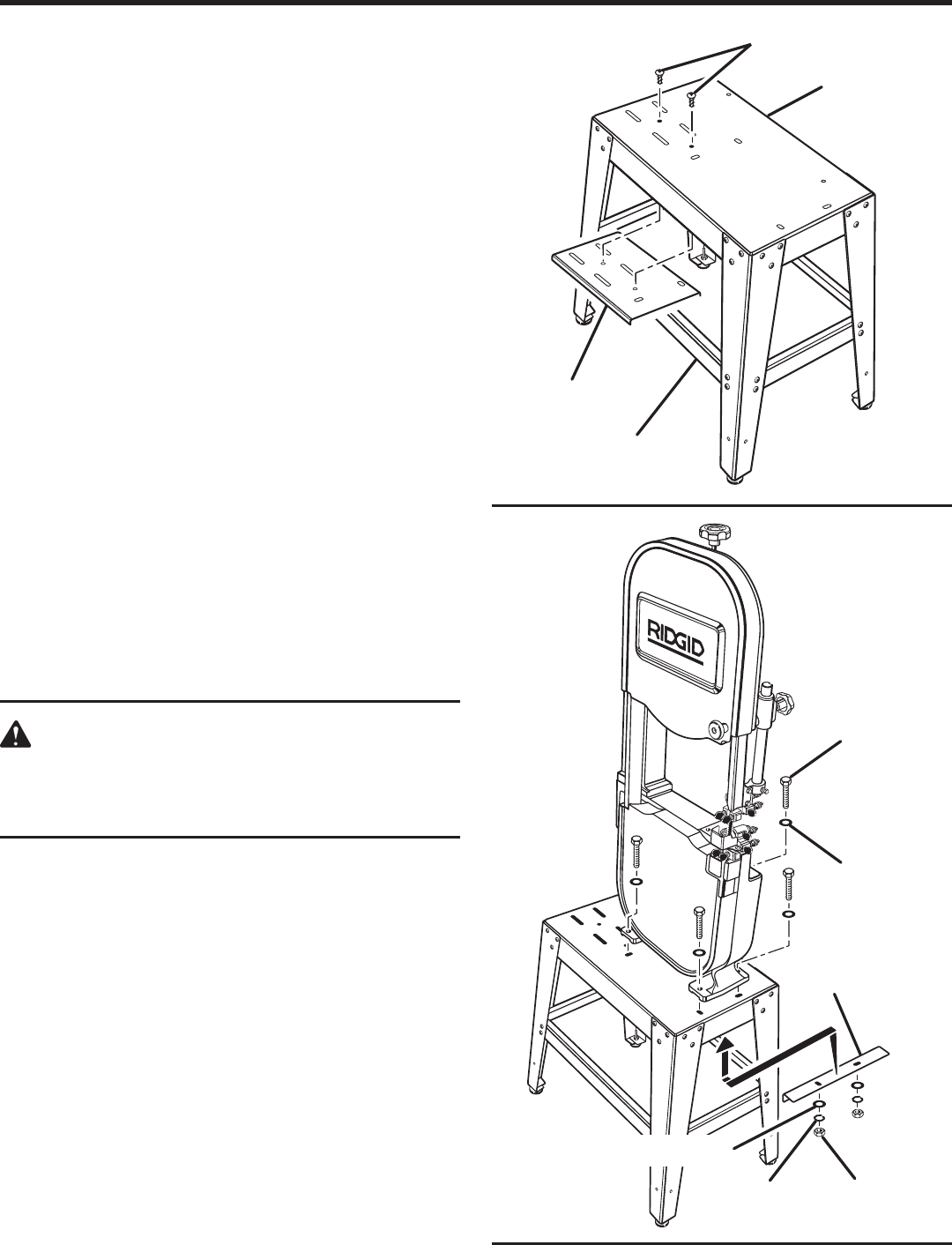
n Place motor support under the base.
n Insert screws through holes in the base and thread into
motor support as shown.
n Tighten all stand fasteners at this time.
n With the aid of a second person, lift the band saw out of
the shipping container and place onto the base. Be sure
front of saw faces leg stand front by aligning holes.
CAUTION:
Do not lift the saw without help. Hold it close to
your body. Keep your knees bent and lift with your
legs, not your back. Ignoring these precautions
can result in back injury.
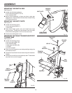
MOUNTING BAND SAW TO LEG STAND
See Figure 13.
n Locate the following hardware:
4 hex head bolts, (M8 x 35)
8 washers, (M8)
4 lock washers, (M8)
4 hex nuts, (M8)
1 plate support
n Place the saw body on the leg stand. Line up holes in
saw body with holes in stand, as shown.
n Place support plate to the underside of stand, as
shown.
n Insert a bolt through a washer, then through a hole in the
saw base and a hole in the leg stand. Add a washer, lock
washer and hex nut. Hand tighten.
n Repeat for remaining holes. Tighten all hardware with a
wrench. You may find it helpful to use one wrench to hold
the head of the bolt and one to tighten the hex nut.
Fig. 12
MOTOR
SUPPORT
SCREWS
LEG STAND
ASSEMBLY
BASE
Fig. 13
P
L
U
L
HEX BOLTS
WASHERS
LOCK
WASHERS
HEX NUTS
PLATE
SUPPORT
WASHERS