


17
ASSEMBLY
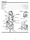
Fig. 15
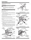
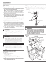
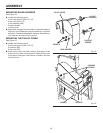
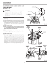
MOUNTING THE MOTOR ASSEMBLY
See Figure 14.
n Locate the following items:
4 hex bolts, (M8 x 35)
8 washers, (M8)
4 lock washers, (M8)
4 hex nuts, (M8)
4 rubber grommets
1 motor with switch assembly
n To mount motor, place four rubber grommets over holes
in leg stand.
NOTE: Use of rubber grommets is essential for eliminating
excessive vibration.
n Set motor on rubber grommets and fasten to leg stand
using hex head bolts, washers, lock washers, and hex
nuts, as shown. Do not tighten at this time.
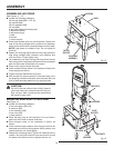
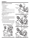
INSTALLING THE V-BELT
See Figures 15 - 17.
n Locate the following item:
1 V-belt
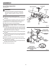
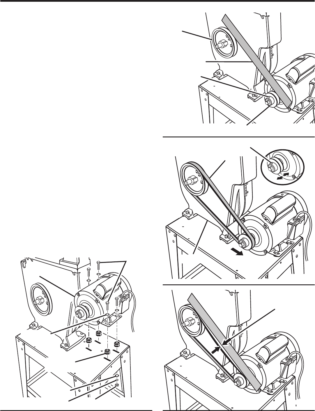
n Align the inside edge of the motor pulley with the inside
edge of the large pulley using a straight edge. With a 3mm
hex wrench, adjust one or both pulleys by loosening the
set screw and moving the pulley(s) until they line up with
each other. Tighten set screws.
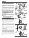
n Place V-belt over both pulleys.
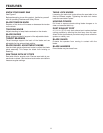
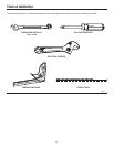
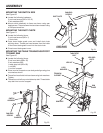
n Tension V-belt by moving motor away from the saw body
and tighten the motor mount nuts. Do not overtighten
motor mount bolts. Tighten just enough to tension belt.
Belt is properly tensioned when finger pressure between
the two pulleys causes approximately 1/2 in. deflection.
Fig. 14
V - BELT
HEX BOLTS
MOTOR
SET SCREW
STRAIGHT EDGE
LARGE PULLEY
MOTOR PULLEY
SET SCREW
PROPER TENSION
APPROXIMATELY 1/2 IN.
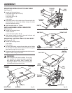
Fig. 16
HEX NUTS
WASHERS
LOCK WASHERS
WASHERS
RUBBER
GROMMETS
Fig. 17
SAW BODY
TENSION
DIRECTION