


23
THUMB SCREWS
0°
15
°
30
°
4
10
°
O
FF
O
ON
I
P
U
S
H
P
U
L
L
P
L
U
L
ASSEMBLY
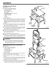
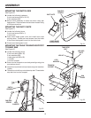
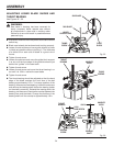
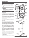
ADJUSTING UPPER BLADE GUIDE ASSEMBLY
See Figures 32 - 33.
n Unplug the saw and remove switch key.
n Loosen blade guard adjustment knob and raise or lower
upper blade guide assembly to just above the material
being cut.
n Tighten blade guard adjustment knob. Make sure blade
guides are still flat to the blade. If adjustment is necessary,
loosen blade guard adjustment knob and rotate assembly
until blade guides are flat to the blade.
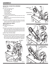
n The upper blade guide is spring loaded. To adjust the
tension on the spring, remove blade guard adjustment
knob, tighten or loosen set screw until desired tension is
reached, and replace blade guard adjustment knob.
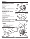
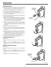
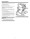
ADJUSTING UPPER BLADE GUIDES AND
THRUST BEARING
See Figures 33 - 34.
WARNING:
Blade guard has been removed for picture clarity.
Never operate the band saw without all guards in
place and in working order. Failure to do so could
result in possible serious personal injury.
n Unplug the saw and remove switch key.
n Blade must already be tensioned and tracking properly.
n Loosen thumb screws and move blade guides as close to
the blade as possible without pinching it. The thickness
of a dollar bill on each side of blade is a good rule of
thumb.
n Tighten thumb screws.
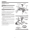
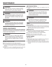
n Loosen thumb screw and turn knurled knob to move
the blade guide bracket in or out until the front edge of
the blade guides are just behind the “gullets” of the saw
teeth.
n Tighten thumb screw.
n Loosen thumb screw and turn knurled knob to move the
thrust bearing in or out until the bearing is 1/64 in. behind
the blade.
n Tighten thumb screw.
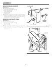
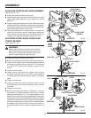
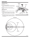
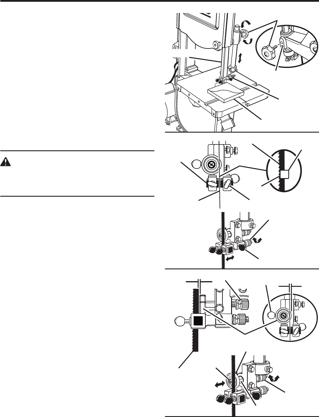
n Blade thrust bearing should be adjusted so that the
back edge of the blade overlaps the front face of the ball
bearing approximately 1/8 in. To change position of the
bearing, remove screw bearing, and back off knurled knob
completely to remove the bearing shaft. Notice the bearing
holder on the shaft is eccentric. Reinstall the bearing shaft,
the bearing, and the screw. Examine the overlap between
the bearing face and the blade. Change the position of
the bearing shaft until the overlap is approximately 1/8
in.
Fig. 32
Fig. 33
Fig. 34
BLADE GUARD
ADJUSTMENT KNOB
BLADE GUIDE
ASSEMBLY
WORKPIECE
SET SCREW
BLADE GUARD
UPPER
BLADE
GUIDES
SAW BLADE
THUMB SCREWS
GULLET
BLADE
GUIDES
SAW BLADE
THRUST BEARING
1/64 IN.
KNURLED KNOB
THUMB SCREW
1/8 IN.
SAW BLADE
THUMB
SCREW
KNURLED KNOBS
KNURLED KNOB
BEARING SHAFT
BEARING
SCREW