


28
LOWER WHEEL
ADJUSTMENTS
WARNING:
Failure to turn the saw off, remove the switch key,
and unplug the saw could result in accidental
starting causing possible serious personal
injury.
WARNING:
Always wear safety goggles or safety glasses with
side shields to protect your eyes while uncoiling
band saw blades. Failure to do so could result in
possible serious personal injury.
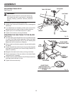
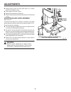
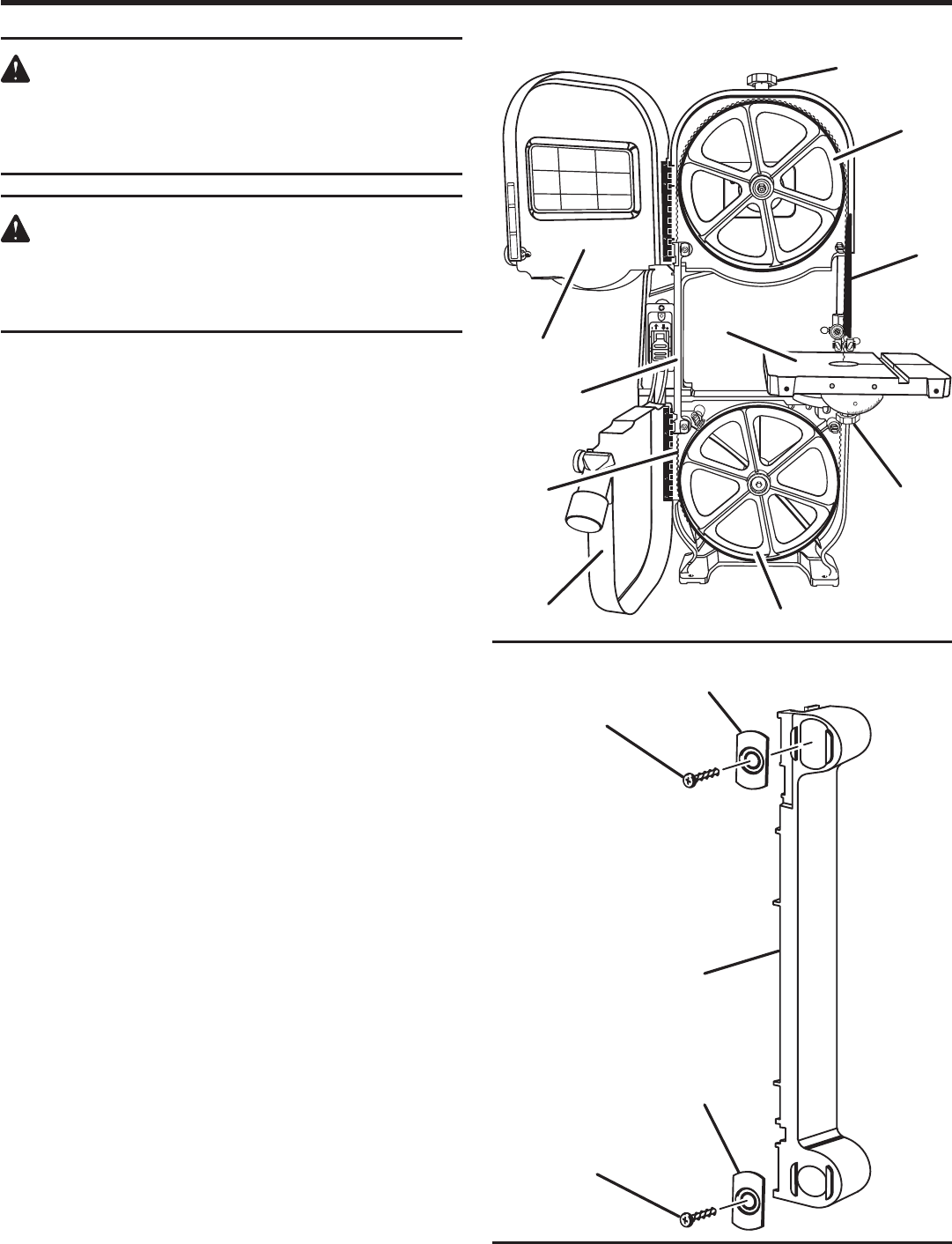
INSTALLING AND ADJUSTING THE BLADE
See Figures 40 - 41.
n Turn the saw off, remove the switch key, and unplug the
saw from the power source.
n Remove the table pin and the throat plate from the saw
table.
n Turn the blade guard adjustment knob counterclockwise
to unlock the blade guide assembly. Raise the blade guide
assembly as high as it will go. Turn the blade guard
adjustment knob clockwise to retighten.
n Turn the blade tension knob counterclockwise to release
tension on the blade.
n Insert screwdriver through table insert hole to loosen the
screw holding the guard under the saw table. Rotate guard
out of the way.
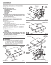
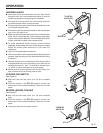
n Open the upper and lower cover by pulling on the
knobs.
n Remove the screws and clamps from the rear blade guard.
Remove rear blade guard.
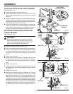
n Wearing gloves, carefully remove the old blade. Turn the
blade to pass through the slot in the saw table.
n Carefully uncoil the new blade at arms length. If the new
blade was oiled to prevent rusting, it may need to be
wiped to keep the oil from your workpiece. Carefully wipe
in the same direction the teeth are pointing so the rag
does not catch on the teeth of the blade.
NOTE: The blade may need to be turned inside out if the
teeth are pointing in the wrong direction. Hold the blade
with both hands and rotate it inward.
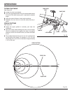
n With the teeth of the blade toward the front of the saw
and facing downward, slide the blade through the saw
table slot.
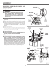
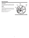
n Place blade in the upper and lower blade guides, and
over the upper wheel and under the lower wheel.
n Turn the blade tension knob clockwise to tension the blade.
See Assembly section "Adjusting Blade Tension".
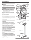
n Adjust the tracking of the blade. See Assembly section
"Tracking the Blade".
n Replace rear blade guard. Secure with screws and
clamps.
Fig. 40
10°
0°
15°
30°
45°
Fig. 41
LOCK KNOBS
UPPER COVER
LOWER COVER
REAR
BLADE GUARD
REAR BLADE
GUARD
BLADE
GUARD SCREW
BLADE
GUARD CLAMP
BLADE
GUARD CLAMP
BLADE
GUARD SCREW
BLADE
GUARD
SAW
BLADE
UPPER
WHEEL
BLADE
TENSION KNOB
SAW
TABLE