


20
P
L
U
L
ASSEMBLY
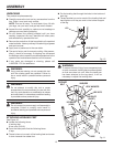
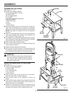
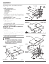
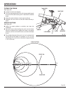
MOUNTING BEVEL SCALE TO SAW TABLE
See Figure 23.
n Locate the following items:
2 flat head screws, (M5 x 0.8-15)
2 washers, (M5)
2 hex nuts, (M5 x 0.8)
1 bevel scale
1 saw table
n Align bevel scale on the inside edge of the saw table with
the text facing out. Insert the screws through the table
and bevel scale as shown.
n Install a washer and nut. Tighten
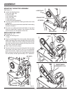
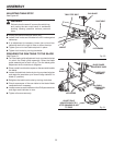
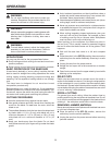
INSTALLING BEVEL SCALE INDICATOR
See Figure 24.
n Locate the following items:
1 scale indicator
1 pan head screw, (M5 x 0.8-6)
n Insert screw through the slot in the scale indicator and
into the trunnion support. Tighten.
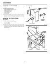
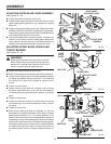
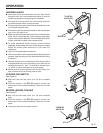
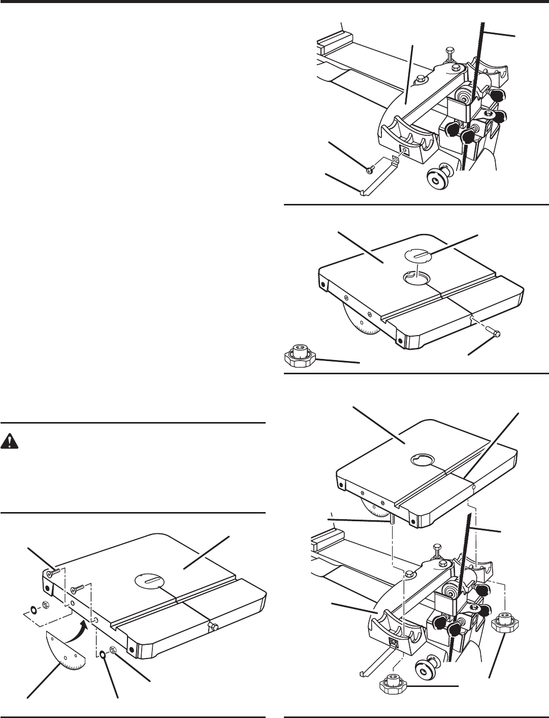
MOUNTING THE SAW TABLE TO SAW BODY
See Figures 25 - 26.
n Locate the following items:
1 saw table
2 lock knobs
n To mount saw table, remove throat plate and pull table
pin out from the table. Rotate saw table 90° and guide
saw blade through slot in saw table.
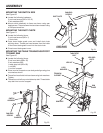
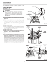
n �Rotate saw table back and place table screws into trunnion
support. Attach using lock knobs.
WARNING:
Unit is shipped with blade installed. Do not plug
in or operate unit unless the blade is adjusted
and aligned per section titled “Installing and
Adjusting the Blade”. Failure to do so could result
in possible serious personal injury.
Fig. 24
Fig. 25
Fig. 26
0°
15
°
30
°
10
°
45
°
P
L
U
L
0°
15
°
30
°
10
°
45
°
0°
15
°
30
°
10
°
45
°
Fig. 23
FLAT HEAT
SCREWS
WASHERS
HEX NUTS
BEVEL SCALE
SAW TABLE
POINTER
PAN HEAD
SCREW
TRUNNION
SUPPORT
SAW TABLE
LOCK KNOBS
TABLE PIN
THROAT PLATE
SAW TABLE
SLOT IN
SAW TABLE
TABLE
SCREWS
TRUNNION
SUPPORT
LOCK KNOBS
SAW
BLADE
SAW
BLADE