


11
FEATURES
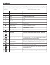
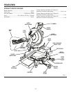
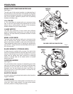
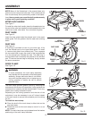
KNOW YOUR COMPOUND MITER SAW
See Figure 1.
The safe use of this product requires an understanding of
the information on the tool and in this operator’s manual as
well as a knowledge of the project you are attempting. Before
use of this product, familiarize yourself with all operating
features and safety rules.
10 in. BLADE
A 10 in. saw blade is included with your compound miter
saw. It is fine for most wood cutting operations, but for fine
joinery cuts or cutting plastic, use one of the accessory
blades available from your nearest dealer.
15 AMP MOTOR
This saw has a powerful 15 amp motor with sufficient
power to handle tough cutting jobs. It is made with all ball
bearings, and has externally accessible brushes for ease
of servicing.
BEVEL LOCK KNOB
The bevel lock knob securely locks your compound miter
saw at desired bevel angles. Positive stop adjustment
screws have been provided on each side of the saw arm.
These adjustment screws are for making fine adjustments
at 0° and 45°. Using the bevel override feature allows up to
48° for bevel cuts.
BLADE WRENCH / STORAGE AREA
A blade wrench is packed with your saw. One end of the
wrench is a phillips screwdriver and the other end is a 5 mm
hex key. Use the hex key end when installing or removing
blade and the phillips end when removing or loosening
screws. A storage area for the blade wrench is located
behind the fence.
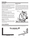
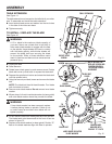
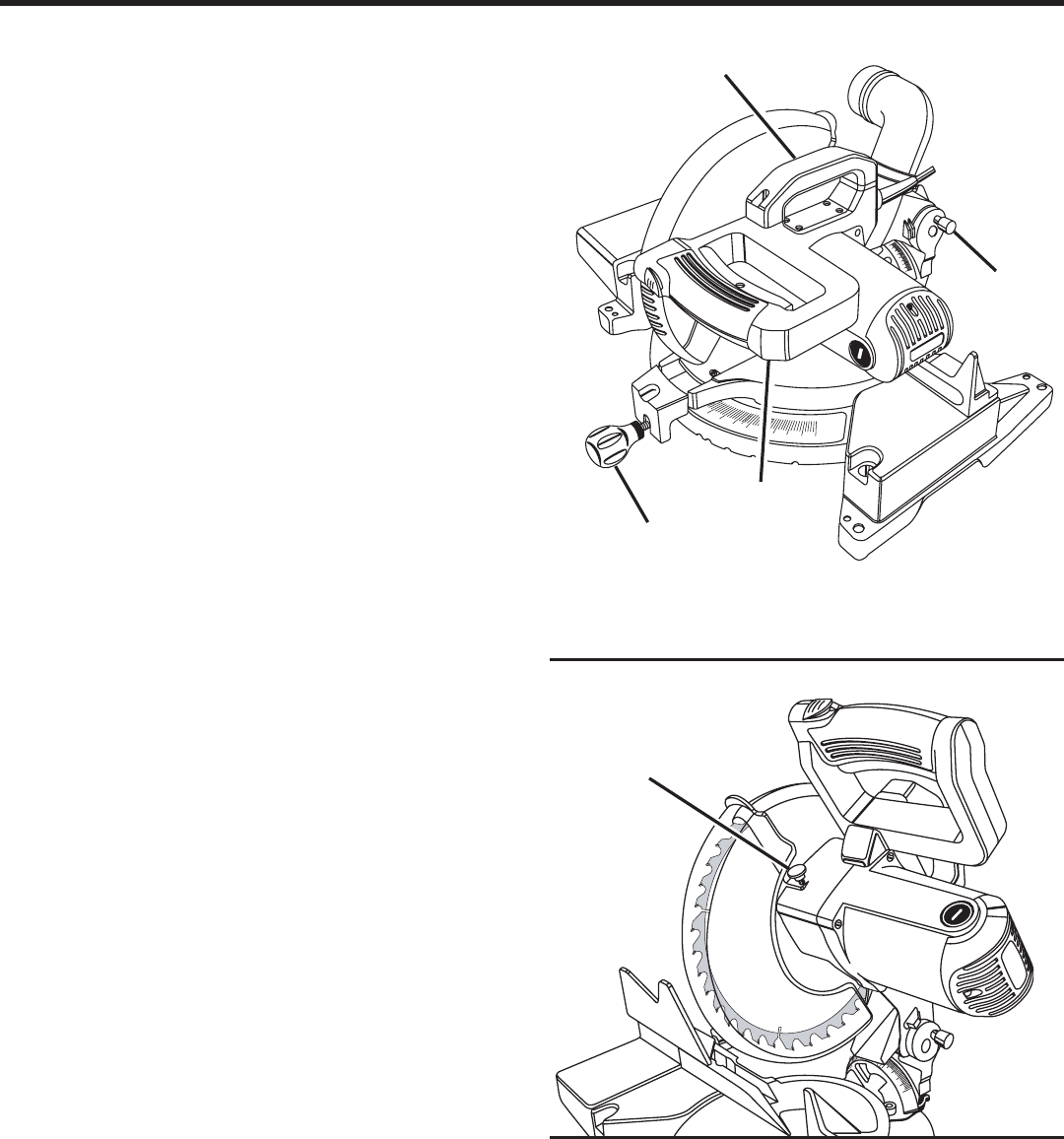
CARRYING HANDLE
See Figure 2.
For convenience when carrying or transporting your miter
saw from one place to another, a carrying handle has been
provided on top of the saw arm as shown in figure 2. To
transport, turn off and unplug your saw, then lower the
saw arm and lock it in the down position. Lock saw arm by
depressing the lock pin.
ELECTRIC BRAKE
An electric brake quickly stops blade rotation after the switch
trigger is released.
LASER GUIDE
For more accurate cuts, a laser guide is included with your
miter saw. When used properly, the laser guide makes
accurate, precision cutting simple and easy.
CARRYING
HANDLE
Fig. 2
SAW ARM LOCKED IN DOWN POSITION
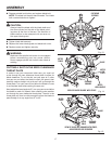
“D” HANDLE
MITER LOCK
HANDLE
LOCK
PIN
SPINDLE
LOCK
BUTTON
Fig. 3