


29
ADJUSTMENTS
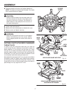
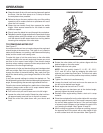
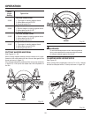
POSITIVE STOP
ADJUSTMENT
FOR 45° ANGLES
Fig. 35
POSITIVE STOP
ADJUSTMENT
FOR ANGLES
UP TO 48°
DEPTH STOP
ADJUSTMENT
SCREW
WARNING:
Before performing any adjustment, make sure the
tool is unplugged from the power supply. Failure
to heed this warning could result in serious per-
sonal injury.
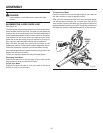
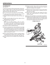
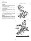
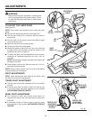
TO ADJUST THE LASER GUIDE
See Figure 34.
NOTE: Avoid direct eye exposure when using the laser
guide.
Set both the bevel angle and the miter table at 0°.
Use the work clamp or a C-clamp to secure a piece of
scrap wood.
Plug the saw into the power source and make a slight
cut to score the wood.
Raise the saw arm and unplug the saw.
Lift and hold the lower blade guard.
Rotate the blade by hand until you can push and hold
the laser button and the laser is near the center of the
workpiece as shown in figure 34.
To adjust the laser, turn the adjustment screw counter-
clockwise or clockwise using the hex key (1/16 in.)
provided.
NOTE: When properly aligned, the laser should be on the
left edge of the kerf.
Once aligned, remove and store the hex key (1/16 in.),
and lower the blade guard.
NOTE: Always make practice cuts on scrap wood before
cutting through your workpiece.
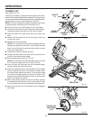
PIVOT ADJUSTMENTS
NOTE: These adjustments were made at the factory and
normally do not require readjustment.
TRAVEL PIVOT ADJUSTMENT
The saw arm should rise completely to the up position
by itself.
If the saw arm does not raise by itself or if there is play
in the pivot joints, have saw repaired at your nearest
AUTHORIZED SERVICE CENTER.
BEVEL PIVOT ADJUSTMENT
The compound miter saw should bevel easily by
loosening the bevel lock knob and tilting the saw arm
to the left.
If movement is tight or if there is play in the pivot, have
saw repaired at your nearest AUTHORIZED SERVICE
CENTER.
Fig. 34
HEX
KEY
LASER
MARK
LASER
BUTTON
ADJUSTMENT
SCREW
APERTURE