


24
OPERATION
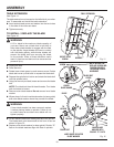
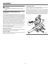
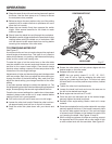
Grasp the stock firmly with one hand and secure it against
the fence. Use the work clamp or a C-clamp to secure
the workpiece when possible.
Before turning on the saw, perform a dry run of the cutting
operation just to make sure that no problems will occur
when the cut is made.
Grasp the saw handle firmly then squeeze the switch
trigger. Allow several seconds for the blade to reach
maximum speed.
Slowly lower the blade into and through the workpiece.
Release the switch trigger and allow the saw blade to stop
rotating before raising the blade out of workpiece. Wait
until the electric brake stops blade from turning before
removing the workpiece from miter table.
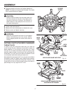
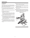
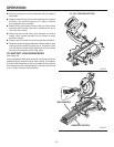
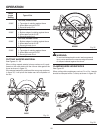
TO COMPOUND MITER CUT
See Figure 27.
A compound miter cut is a cut made using a miter angle and
a bevel angle at the same time. This type of cut is used to
make picture frames, cut molding, make boxes with sloping
sides, and for certain roof framing cuts.
To make this type of cut the control arm on the miter table
must be rotated to the correct angle and the saw arm must
be tilted to the correct bevel angle. Care should always
be taken when making compound miter setups due to the
interaction of the two angle settings.
Adjustments of miter and bevel settings are interdependent
with one another. Each time you adjust the miter setting you
change the effect of the bevel setting. Also, each time you
adjust the bevel setting you change the effect of the miter
setting.
It may take several settings to obtain the desired cut. The
first angle setting should be checked after setting the second
angle, since adjusting the second angle affects the first.
Once the two correct settings for a particular cut have been
obtained, always make a test cut in scrap material before
making a finish cut in good material.
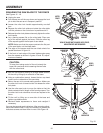
Pull out the lock pin and lift saw arm to its full height.
Loosen the miter lock handle. Rotate the miter lock han-
dle approximately one-half turn to the left to loosen.
Press the miter lock plate down with your thumb and
hold.
Rotate the miter table until the pointer aligns with the
desired angle on the miter scale.
Release the miter lock plate.
NOTE: You can quickly locate 0°, 11.25°, 15°, 22.5°,
31.6°, and 45° left or right by releasing the miter lock
plate as you rotate the control arm. The miter lock plate
will seat itself in one of the positive stop notches, located
in base.
Tighten the miter lock handle securely.
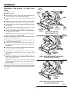
Loosen the bevel lock knob and move the saw arm to
the left to the desired bevel angle.
Bevel angles can be set from 0° to 48°.
Once the saw arm has been set at the desired angle,
securely tighten the bevel lock knob.
Recheck miter angle setting. Make a test cut in scrap
material.
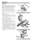
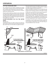
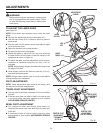
Place the workpiece flat on the miter table with one edge
securely against the fence. If the board is warped, place
the convex side against the fence. If the concave edge
of a board could collapse on the blade at the end of the
cut, jamming the blade. See Figures 31 and 32.
When cutting long pieces of lumber or molding, support
the opposite end of the stock with a roller stand or with
a work surface level with the saw table. See Figure 29.
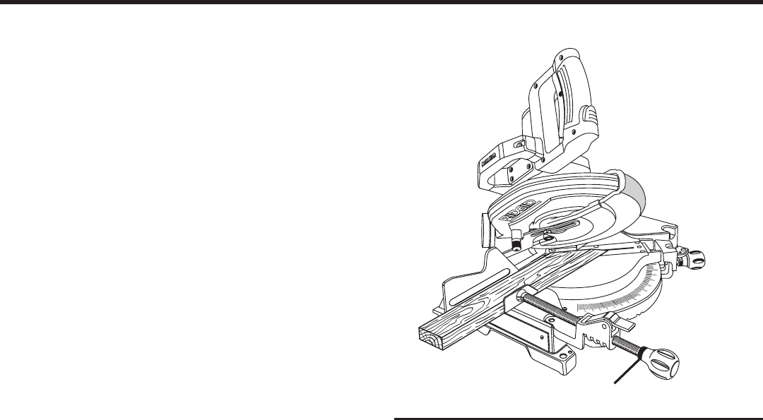
Fig. 27
WORK CLAMP
COMPOUND MITER CUT