


18
MITER
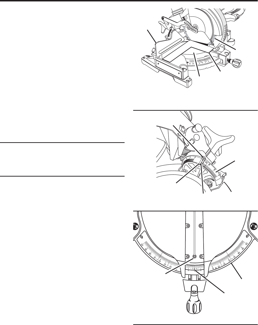
FENCE
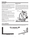
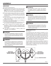
VIEW OF BLADE NOT SQUARE WITH FENCE,
ADJUSTMENTS ARE REQUIRED
FRAMING
SQUARE
MITER
TABLE
BLADE
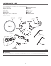
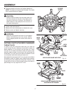
SCALE
INDICATOR
MITER
SCALE
INDICATOR
SCREW
SCALE
INDICATOR
BEVEL
SCALE
INDICATOR
SCREW
INDICATOR
POINT
ASSEMBLY
Fig. 18
Fig. 17
SQUARING THE SAW BLADE TO THE FENCE
See Figures 13 - 18.
Unplug the saw.
Pull the saw arm all the way down and engage the lock
pin to hold the saw arm in transport position.
Loosen the miter lock handle approximately one-half
turn.
Depress the miter lock plate and rotate the miter table
until the pointer on the control arm is positioned at 0
°
.
Release the miter lock plate and securely tighten the miter
lock handle.
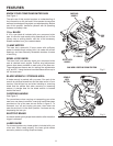
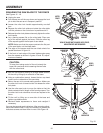
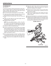
Lay a framing square flat on the miter table. Place one
leg of the square against the fence. Slide the other leg
of the square against the flat part of saw blade.
NOTE: Make sure that the square contacts the flat part
of the saw blade, not the blade teeth.
The edge of the square and the saw blade should be
parallel as shown in figure 14.
If the front or back edge of the saw blade angles away
from the square as shown in figures 15 and 16, adjust-
ments are needed.
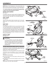
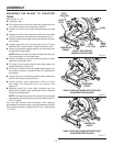
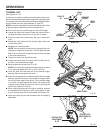
CAUTION:
To keep from losing control of the unit, steady the
base with one hand while loosening the two bolts
with the other hand.
With the unit securely resting on a large stable surface,
tilt the unit by lifting up on one side of the base.
Using a combination wrench, loosen the two cap head
screws on the underside of the saw table.
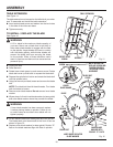
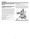
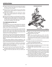
Return the saw to its normal resting position. Make sure
the miter lock knob is loose but do not release the miter
lock plate.
Use the miter saw knob to move the table so that the
blade contacts the full length of the framing square. Turn
the miter lock knob clockwise to lock saw square to the
fence.
Tilt the unit by lifting up on one side of the base and
tighten cap head screws.
Recheck blade squareness to fence and readjust if
necessary.
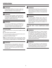
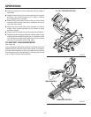
Your saw has several scale indicators. After squaring adjust-
ments have been made, it may be necessary to loosen the
indicators screws and reset them to zero.
See Figure 18.
Fig. 16