


19
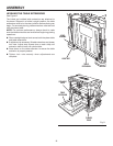
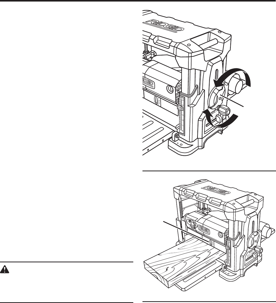
Fig. 12
dePth
GAuGe
OPERATION
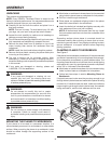
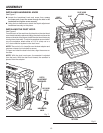
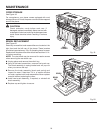
ADJUSTING THE PLANING DEPTH
See Figure 11.
The depth adjustment handwheel is used to set the amount
of wood being removed in a planing pass. Never make a
planing cut deeper than 1/8 in. for material up to 6 in. wide
or 1/16 in. for material between 6 in. and 13 in. wide.
NOTE: Do not continuously use the planer at the maximum
depth of cut (1/8 in.) as it will damage the motor.
Rotate the depth adjustment handwheel to position the
cutterhead at the desired planing depth. Each full revolution
of the handle will raise or lower the cutterhead 1/16 in.
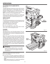
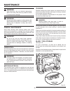
DEPTH GAUGE
See Figure 12.
The depth gauge indicates the amount of wood being removed
in a planing pass. The workpiece must be positioned under
the depth gauge on the front of the planer.
Never make a planing cut deeper than:
1/8 in. for material up to 6 in. wide
1/16 in. for material 6 in. - 13 in. wide
Do not continuously use the planer at the maximum depth
of cut, 1/8 in., as it will damage the motor.
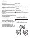
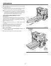
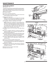
PLANING
See Figure 13.
Use scrap wood for your first planing attempt. Once you
have planed the wood, check all measurements for accuracy.
If measurements are not exact, see Adjustment section for
further instruction.
Before each use of the planer, check for loose fasteners,
fittings, or hardware; be sure the dust hood is securely
mounted; and ensure the blade cutter rotates freely. Lower
the cutterhead assembly to approximately 1 in. above the
planer table surface. Without putting any load on the planer,
test the motor by turning the planer on and allowing it to
reach full speed. If the planer sounds excessively loud or
has excessive vibration, turn off the machine immediately
and check again for any loose hardware, retightening any
you may find.
WARNING:
To avoid serious personal injury, do not stand
directly in line with the front or rear of the planer.
If an object is thrown from the planer, it will travel
in this direction.
Stand to one side of the planer infeed area.
Turn switch ON ( l ).
Lift the work to the table by grasping the edges of the
board at approximately the middle of the length. Rest the
board end on the feed table and direct the board into the
planer.
NOTE: Boards longer than 24 in. should have additional
support from free-standing material stands.
Fig. 11
dePth
AdjuStment
hAndwheel
1
1
1
1
1
1
3
3
2
2
"
"
4
4
4
4
8
1
1
1