


12
1
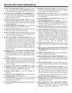
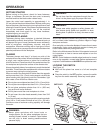
Repeat
Cut
A
-
-
1
1
1
1
1
3
3
2
2
"
"
4
4
4
4
8
1
1
1
3
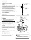
1/8
3/32
1/16
1/32
0
2.5
2
1.5
1
.5
0
Ind
I
Cut
6
5
4
2
1
0
0
1
2
3
4
5
6
7
8
9
10
11
12
13
14
15
3
1
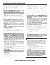
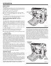
Repeat
Cut
A
-
-
1
1
1
1
1
3
3
2
2
"
"
4
4
4
4
8
1
1
1
6
5
4
2
1
0
0
1
2
3
4
5
6
7
8
9
10
11
12
13
14
15
3
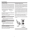
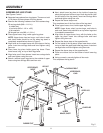
ASSEMBLY
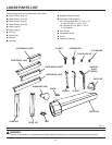
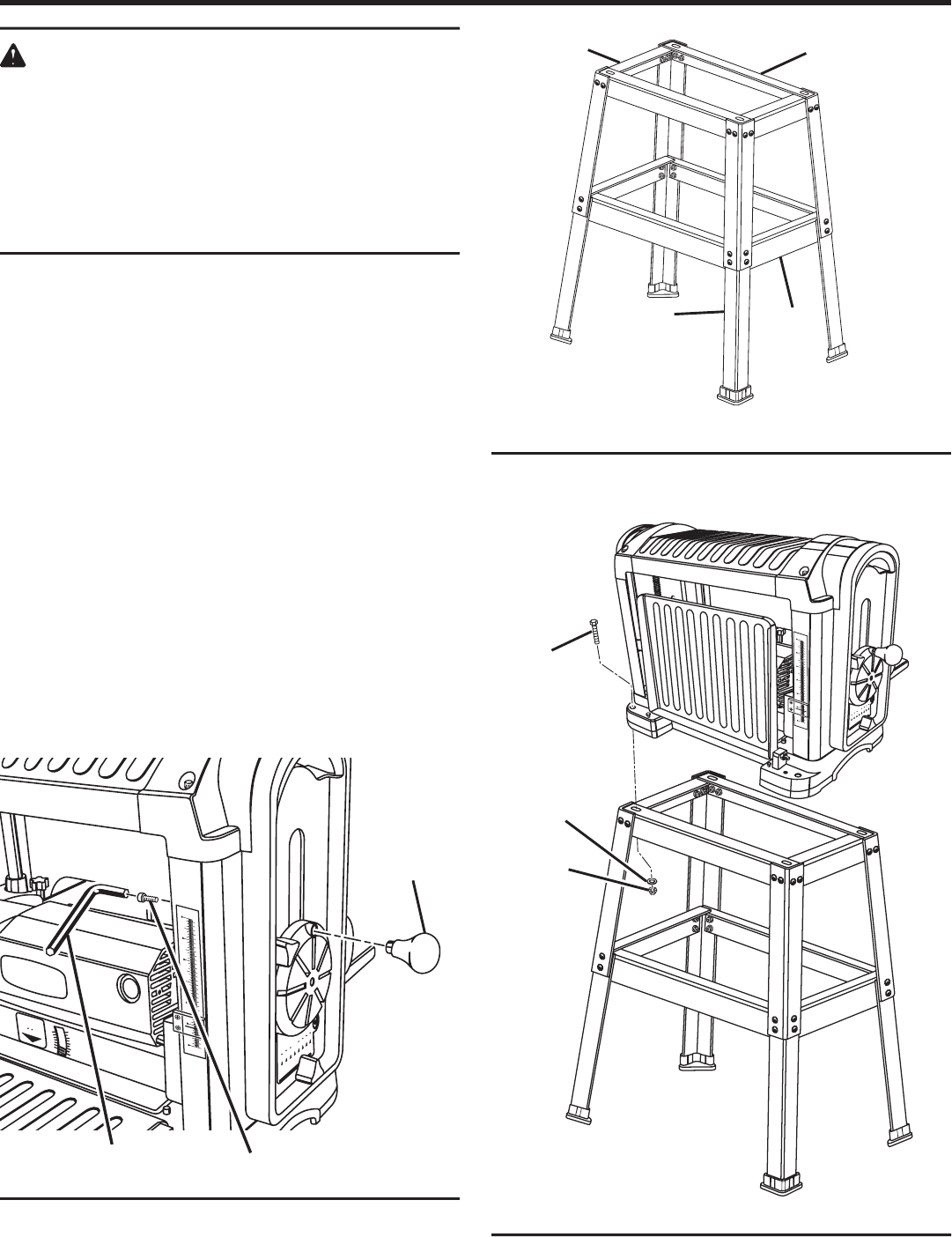
LOWER LEG
LOWER
BRACE,
SHORT
WARNING:
To prevent accidental starting that could cause pos-
sible serious personal injury, assemble all parts,
make sure all adjustments are complete, and make
sure all fasteners are secure before connecting tool
to power supply. The tool should never be con-
nected to power supply when you are assembling
parts, making adjustments, installing or removing
blades, or when not in use.
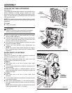
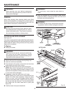
INSTALLING HANDWHEEL KNOB
See Figure 6.
Remove the handwheel knob and screw from the
hardware bag.
Turn the depth adjustment handwheel until the hole for
the handwheel knob is aligned with the slot in the planer
housing.
Place the handwheel knob over the hole and tighten it
using the screw.
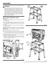
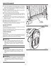
MOUNTING THE PLANER TO THE LEG STAND
See Figure 8.
Turn leg stand upright as shown in figure 7.
Carefully place planer on the top of the leg stand. Align
holes in the planer base with the holes in the leg stand.
Insert the hex bolts in each of the four holes and secure
using flat washers and hex nuts.
Tighten all hardware with wrenches. You may find it
helpful to use one wrench to hold the head of the bolt
and one to tighten the hex nut.
UPPER
BRACE,
SHORT
HEX
BOLT
HEX
NUT
UPPER
BRACE,
LONG
Fig. 8
Fig. 7
WASHER
Fig. 6
HANDWHEEL
KNOB
SCREW
HEX KEY