


MAINTENANCE
WARNING:
When servicing, use only identical replacement
parts. Use of any other part may create a hazard or
cause product damage.
GENERAL
Avoid using solvents when cleaning plastic parts. Most
plastics are susceptible to damage from various types of
commercial solvents and may be damaged by their use. Use
clean cloths to remove dirt, carbon dust, etc.
CAUTION:
Do not at any time let brake fluids, gasoline, petro-
leum-based products, penetrating oils, etc. come in
contact with plastic parts. They contain chemicals
that can damage, weaken or destroy plastic.
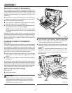
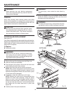
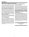
CUTTER BLADE REPLACEMENT
See Figure 18.
Your planer is equipped with replaceable/disposable double-
edged cutter blades attached to a rotating cutter block. Worn
cutter blades will affect cutting accuracy and may produce
ridges on the workpiece.
To Replace:
Unplug your planer.
WARNING:
Failure to turn the tool off, remove the switch key,
and unplug the tool before servicing or making
adjustments could result in accidental starting caus-
ing possible serious personal injury.
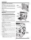
Remove the top of the housing cover by lifting it up.
Lower the cutter head assembly.
From the back of the planer, remove the two dust chute
knobs holding the dust chute in place.
Remove the dust chute and the cutter head guard.
NOTE: When cutter head guard is removed, the cutter
head lock will engage when the head is rotated. Do not
operate thickness planer without the dust chute in place
or your planer will be damaged.
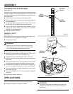
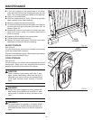
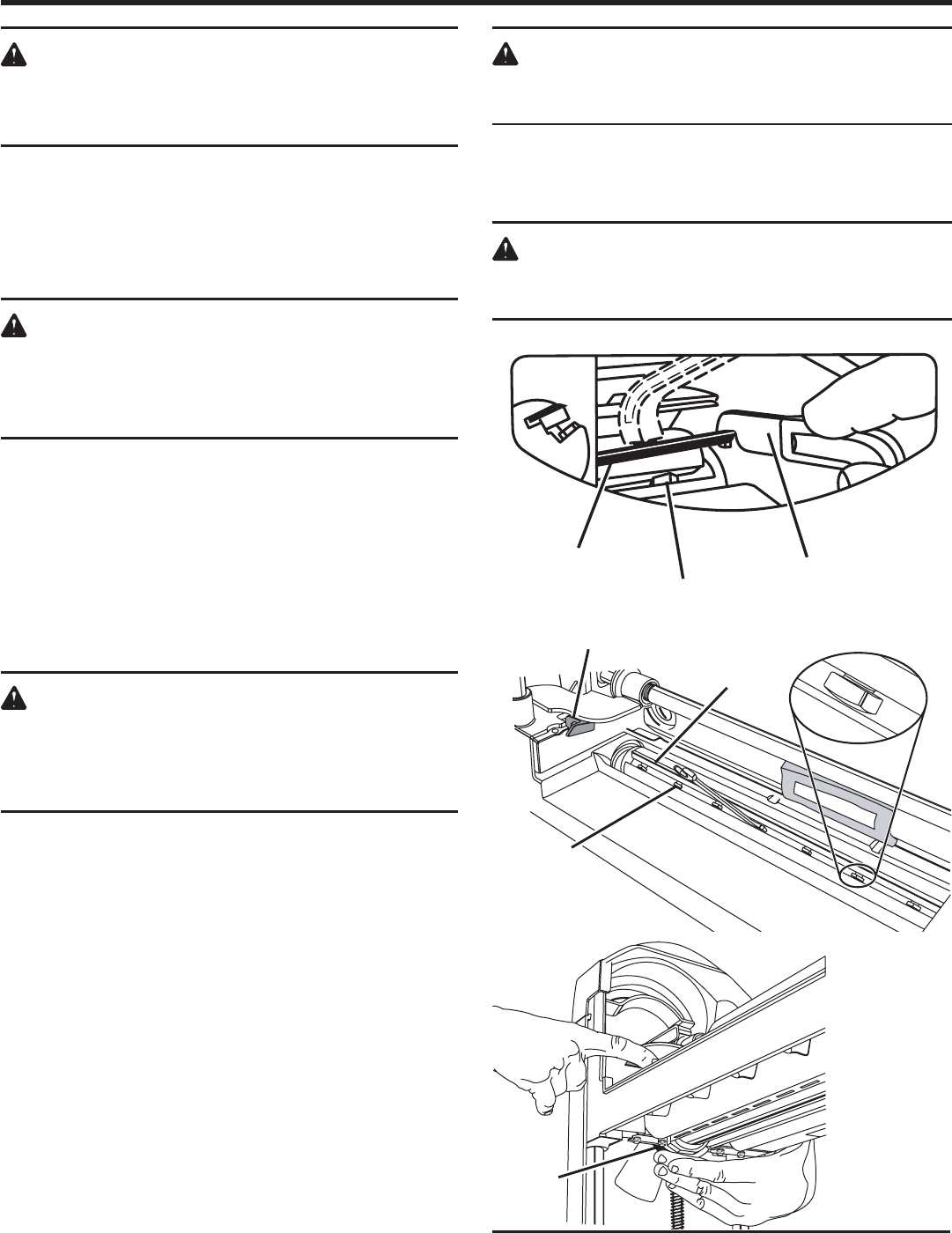
If necessary, rotate the cutter block until it locks.
NOTE: Rotating the cutter block is accomplished from
beneath the cutter head assembly. Using the planer
table as a mirror, touch the threaded spindle where it
attaches to the planer table. Carefully move your fingers
up until you touch the drive belt. Turn the drive belt with
your fingers until the cutter head locks in place (
see
Figure 18).
Carefully loosen the square head bolts.
WARNING:
To avoid injury, never rotate the cutter block by
hand.
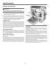
Using the notched end of the magnetic blade wrench,
remove the blade by hooking the notch over the end of
the blade and pulling straight out.
WARNING:
To reduce the risk of injury, never perform the plan-
ing operation with the cutter head guard removed.
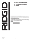
Fig. 18
18
BLADE
DRIVE
BELT
SQUARE
HEAD
BOLTS
CUTTER LOCK
CUTTERHEAD
(SIDE VIEW)
MAGNETIC
BLADE WRENCH
BLADE
SQUARE
HEAD BOLTS