


assembly and alignment
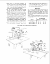
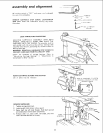
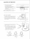
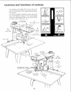
3. Lower arm until saw blade just clears the front table.
Lock the yoke clamp handle and bevel lock lever.
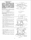
4. Place a framing square on the table as shown and
position the blade and square until the leg of the square
just contacts a tooth of the blade. Mark this tooth.
NOTE: The framing (or combination) square must be
"true" -- see start of "Assembly and
Alignment" section on p. 8 for checking
method."
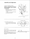
5. When the carriage is moved back and forth on the arm,
the marked tooth should just touch the square at all
poults. If marked tooth moves into square or away
from square the following adjustments are required:
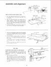
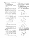
a. Loosen (3) 3/8 - 16 set screws in arm latch at rear
of arm.
b. Move the arm in proper direction to make marked
tooth follow edge of square when the saw blade is
moved along arm in a "cross cut" manner.
c. Lock arm latch.
d. RETIGHTEN (3) setscrews in arm latch as tight as
possible and recheck "cross cut" travel.
NOTE: This squaring of the cross cut travel will
simultaneously set BOTH of the 45 ° miter index
positions.
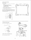
BEVEL LOCK
LEVER
D
_HEX "L" WRENCH
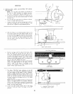
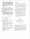
e. Set miter indicator on 0° position as shown.
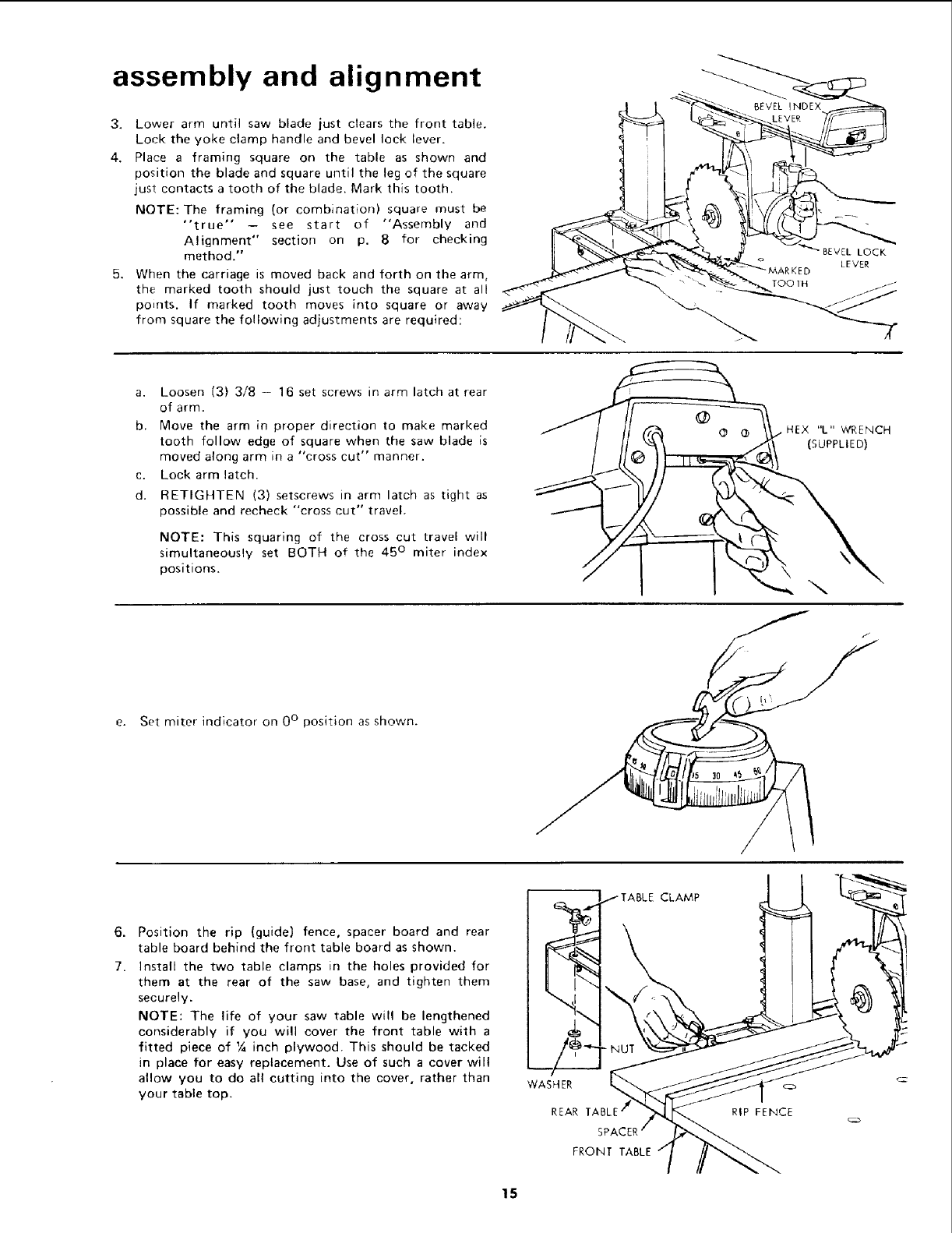
6.
7.
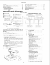
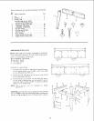
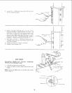
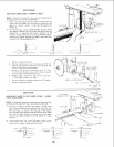
Position the rip (guide) fence, spacer board and rear
table board behind the front table board as shown.
Install the two table clamps in the holes provided for
them at the rear of the saw base, and tighten them
securely.
NOTE: The life of your saw table will be lengthened
considerably if you will cover the front table with a
fitted piece of 1/4inch plywood. This should be tacked
in place for easy replacement. Use of such a cover will
allow you to do all cutting into the cover, rather than
your table top.
WASHER
REAR
FRONT TABLE
CLAMP
RIP FENCE
15