


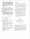
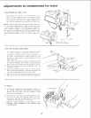
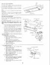
ARM LOCK ADJUSTING WHEEL
Arm control lever operates a brake shoe that locks and
releases the arm, and automatically releases the arm index
pin for 0° & 45 ° m,ter settings.
The lock action should feel tight and secure. Considerable
amount of effort must be applied to the lever to lock the
arm,
NOTE: Lever must be in unlocked position while making
adjustment.
If adjustment is required, turn arm lock adjusting wheel
under front of the arm clockwise to tighten, counter-
clockwise to loosen.
TIGHTEN
ARM LOCK
ADJUS rING WHEEL
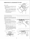
ARM INDEX ROD ADJUSTMENT
At some time it may be necessary to make an adjustment to
the Arm Index Rod, to compensate for wear in the
Indexing System.
An indication that this adjustment must be made is when
one of the following occurs:
IMPORTANT: ARM LOCK/ADJUSTING WHEEL (SEE
ABOVE) MUST BE PROPERLY ADJUSTED AT THIS
TIME.
1. With the arm control lever pulied forward and held
in the "Index Release'" position, the arm cannot be
moved out of the Indexed position. (Index pin not
fully retracting from Index ring).
2. With the arm in one of the Index positions and the
arm contro! lever allowed to rest in the Unlocked
position (with the column tube supports and gibs
adjusted properly eliminating all play in this area).
A slight side to side movement is noticeable at the
front of the arm. (Index pin not fully seated in
Index Ringl.
To make an adjustment to the arm Index rod the following
steps must be taken.
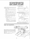
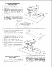
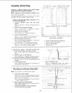
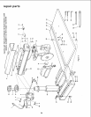
1. Removing Arm Trim (Shroud)
a. Remove miter indicator. Snap fit.
b. Remove miter scale by removing two #10 Pan
Head screws.
c. Remove knobs from arm control lever.
d. Remove stop screw and Iockwasher in arm.
Remove carriage, RE-INSTALL STOP SCREW
AND LOCKWASHER.
e. Grasp arm trim and remove.
f. Remove arm trim pad.
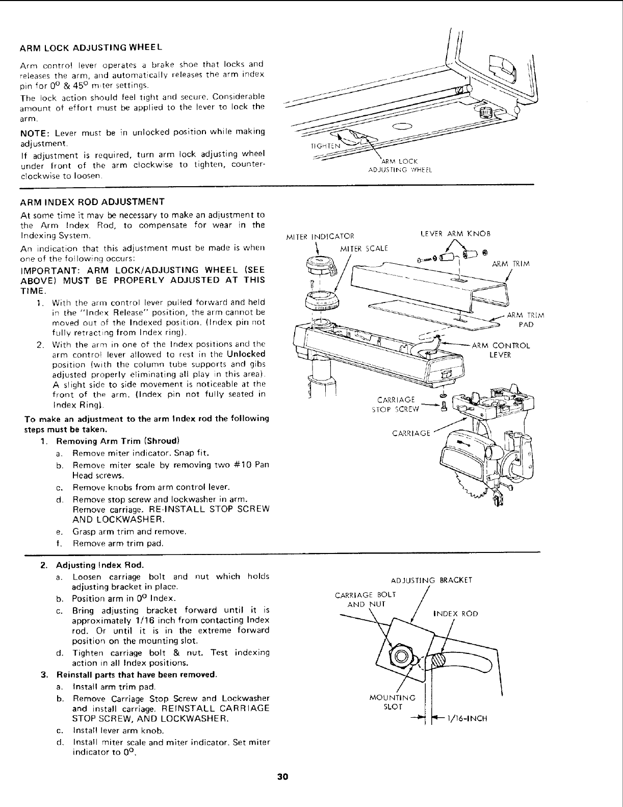
MITER INDICATOR
MITER SCALE
TRIM
PAD
CONTROL
LEVER
CARRIAGE
STOP SCREW --'-_
CARRIAGE
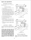
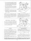
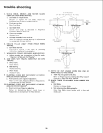
2. Adjusting Index Rod.
a. Loosen carriage bolt and nut which holds
adjusting bracket in place.
b. Position arm in 0° Index.
c. Bring adjusting bracket forward until it is
approximately 1/16 inch from contacting Index
rod. Or until it is in the extreme forward
position on the mounting slot,
d. Tighten carriage bolt & nut. Test indexing
action in all Index positions.
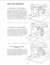
3. Reinstall parts that have been removed.
a. Install arm trim pad.
b. Remove Carriage Stop Screw and Lockwasher
and install carriage. REINSTALL CARRIAGE
STOP SCREW, AND LOCKWASHER.
c. Install lever arm knob.
d. Install miter scale and miter indicator. Set miter
indicator to 0°.
ADJUSTING BRACKET
CARRIAGE BOLT
AND NUT
INDEX ROD
MOUNTING
SLOT
"16-INCH
3O