


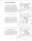
locations and functions of controls
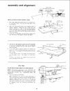
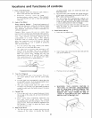
1. Depth of Cut (Elevation)
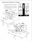
a. The diagram shows the elevation crank which is
used to raise and lower the saw blade.
b. Clockwise rotation raises the blade . . .
counterclockwise rotation lowers it. One complete
turn of the handle will raise or lower the saw blade
Ii16-inch.
2. Angle of Cut (Miter)
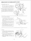
Proper Indexing Method Experienced operators of
woodworking equipment, such as this Craftsman Radial
Saw, acquire the habit of indexing in one direction
only, whenever a new setting is made in preparation for
a different opeTation.
Example: When moving the arm to a miter index
[_osition move it slightly past the desired index position,
then return to the index position carefully to index and
lock. Yoke indexing and bevel indexing carl be
accomplished in a similar manner. This indexing
technique tends to neutralize any stresses impaired
upon saw components and contributes to the high
degree of accuracy the saw is capable of producing
when operated expertly.
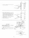
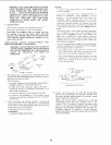
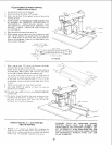
a. The arm control lever locks, unlocks and indexes
the arm for Left and Right Miter cuts.
b. The radial arm has positive index positions at 0°
and 4E ° Left and Right. The arm is rotated by
pulling arm control lever to index release position.
With arm contro! lever released the arm will
automatically index at 0° and 45 ° Left or Right.
After positioning arm to the desired miter angle,
push arm contlol lever to locked position.
UNLOCK INDEX R,ELEASE
LOCK i"_1
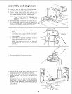
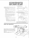
3. Yoke Pivot (Ripping)
a. Two controis are used in this operation. They are:
the swivel latch-pin lever and the yoke clamp
handle.
b. A swivel latch lever automatically indexes the yoke
at each 90 ° position, Pull the spring-loaded swivel
latchdever forward to release this pin.
c. The yoke clamp handle locks the yoke to the
carriage in any position. Pu!l the handle forward to
release the yoke; push the handle rearward to secure
the yoke.
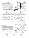
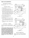
4. Carriage Lock
a. The carriage !ock knob is rotated clockwise to lock
the carriage on the radial arm, and counterclockwise
to release it.
b. When performing crosscutting operations the
carriage lock knob must he rotated
counterclockwise until the carriage is free to travel
along the arm. This knob should be tightened until
the operator is ready to grasp the bevel index
handle and make a cut.
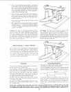
5. Blade Angle (Bevel)
a. The two controls used in angular positioning and
indexing of the motor, to provide the desired
saw-blade (bevel) angle, are: bevel lock lever and
bevel-index lever.
b. The bevel-index scale indicates the angular position
of the motor with respect to horizontal, from 0 ° to
90 ° in either vertical position.
c. The bevel index lever automatically indexes the
motor at 0 °, 45 ° and 90 ° . Move bevel index lever
to the left while positioning the blade, then release
it. At any other position it does not engage.
d. The bevel lock lever locks the motor to the yoke
when the motor is in any position. Pull lever to
release and push to lock.
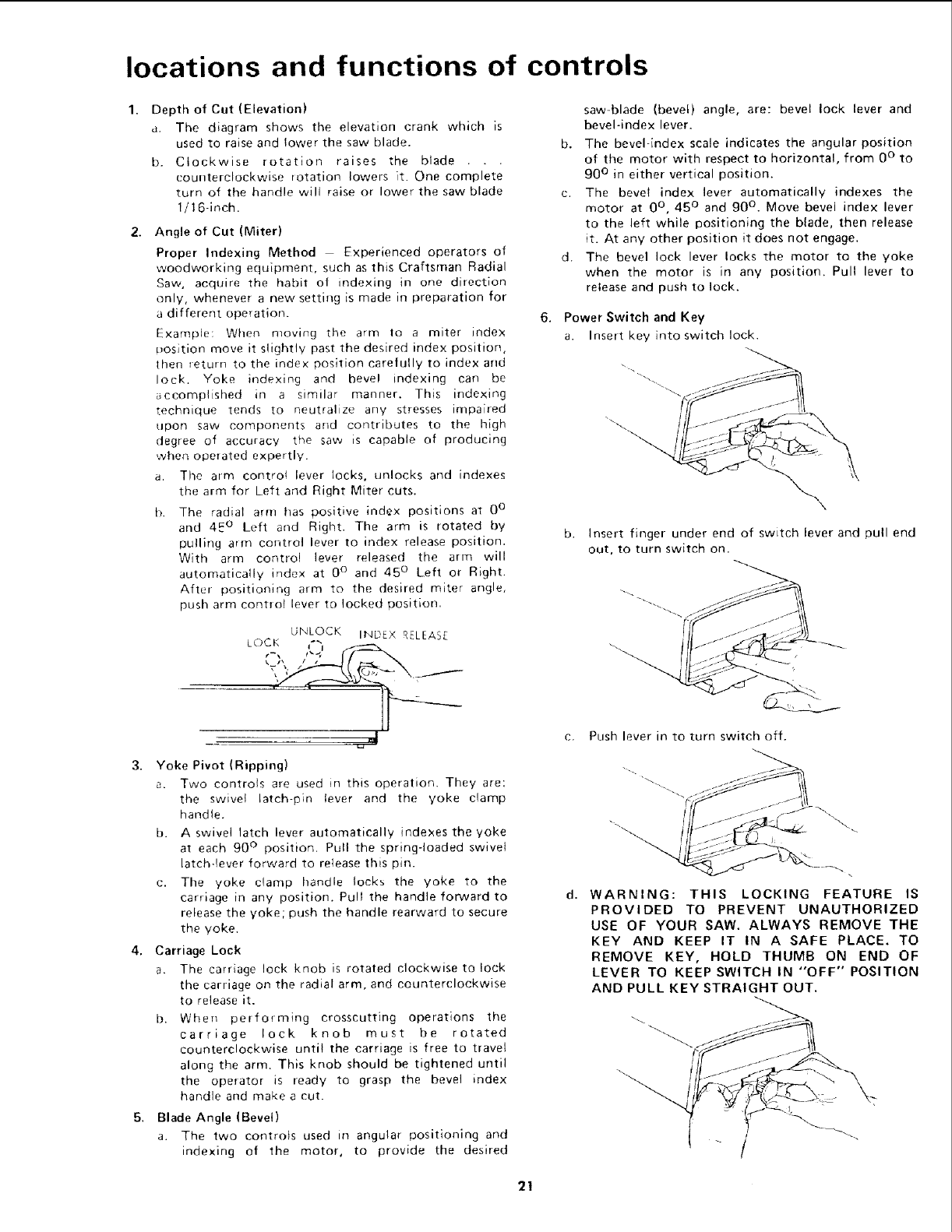
6. Power Switch and Key
a. Insert key into switch lock.
b. Insert finger under end of switch lever and pull end
out, to turn switch on.
c. Push lever in to turn switch off.
d. WARNING: THIS LOCKING FEATURE IS
PROVIDED TO PREVENT UNAUTHORIZED
USE OF YOUR SAW, ALWAYS REMOVE THE
KEY AND KEEP IT IN A SAFE PLACE, TO
REMOVE KEY, HOLD THUMB ON END OF
LEVER TO KEEP SWITCH IN "OFF" POSITION
AND PULL KEY STRAIGHT OUT.
/
/