


adjustments to compensate for wear
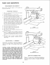
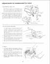
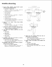
ADJUSTING BEVEL LOCK LEVER
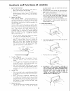
1. The purpose of this lever s to lock the motor at any
angle To adjust, remove the set screw with wrench as
shown. Use the bevel lock lever as a wrench to tighten
the clamp bot. Do Not Over Tighten. Replace bevel
lock lever in locked position and tighten tile set screw
NOTE: The clamp bolt has a left handed thread. Therefore,
to increase the clamping effect, rotate the bevel lock lever
- when used as a wrench - from right to left, or clockwise
when viewed horn above. If you accidentally rotate it the
wrong way and disengage the bolt from the matching steel
nut, it will be necessary to remove the Handle Trim, Yoke
Handle, and Bevel Scale, in order to reinstall the bolt ir_ the
nut.
LOCK LEVER
IN LOCKED POSITION
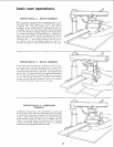
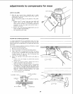
YOKE LOCK HANDLE ADJUSTMENT.
l. This hand!e provides a friction lock between the upper
face of the y)ke and the bottom face of the carriage
It should eliminate any play or rotation between these
two parts when locked. Its proper position for saw
operation is approximately midway between the two
sides of the _,.oke.
When surf cient wear has occured to pmmit the handle
to move cor siderably to the rear, or strike the yoke
before locking, the handle must be adjusted as follows:
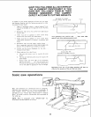
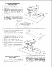
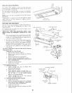
2. Remove carrtage stop screw and Ioekwasher with a 1/4
inch hex-L wrench.
3. Grasp the carriage assembly, move it carefully off the
end of radial arm, holding it parallel to the radial arm
until all carriage bearings are free of their tracks.
4. Rest the motor and carriage assembly on saw work
table and re install carriage stop screw and tockwasher.
CARRIAGE STOP
SCREW
HEX "L" WRENCH
fl/4 INCH)
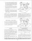
To Readjust
5. Set yoke lock handle at unlocked position. Tighter] nut
with 15/16 wrench, until lock handle locks mid-way
between the two sides of the yoke. Remove carriage
stop screw and Iockwasher.
6. Hold the too[or and carriage assembly parallel to radial
arm and start the rear bearings onto [he t_acks.
Continue to hold the assembly parallel to the tracks
until the forward bearings are on the tracks.
7. Slide the carriage rearward on the radial arm and
INSTALL THE CARRIAGE STOP SCREW AND
LOCKWASH ER.
15/!6 WRENCH
28