


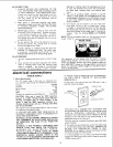
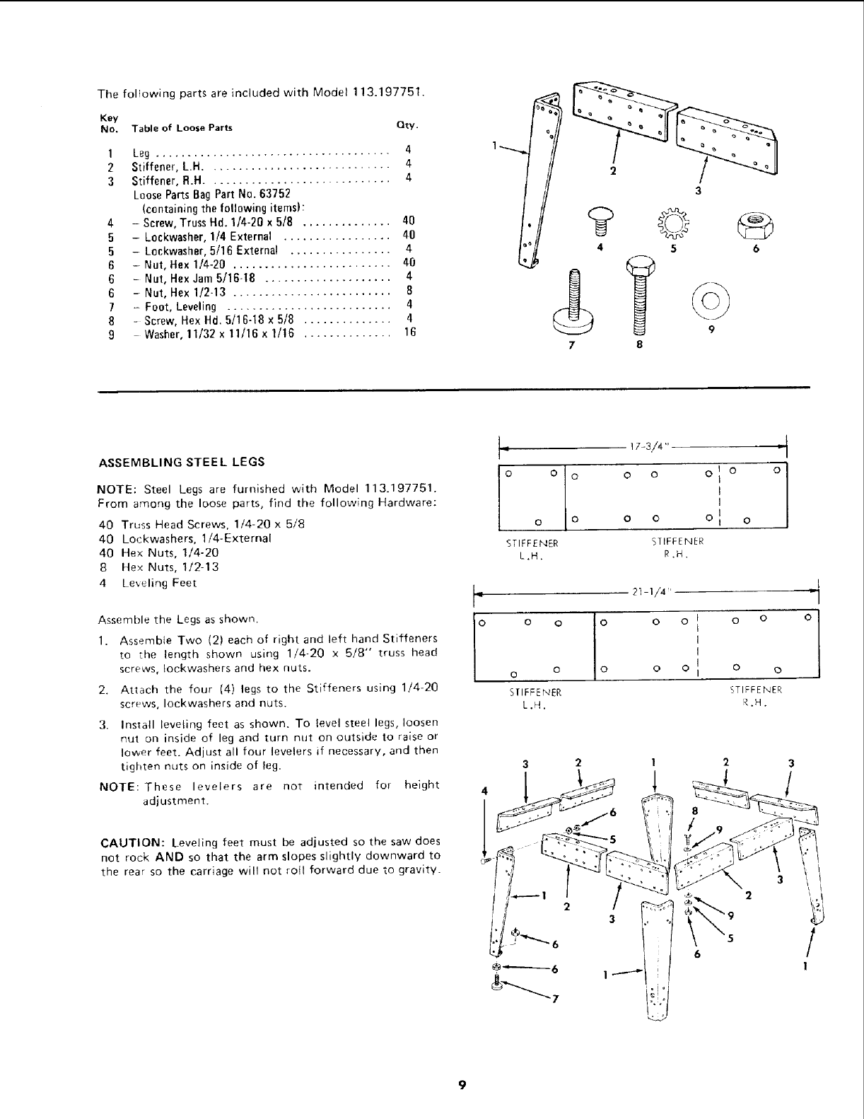
ThefoliowingpartsareincludedwithModel113.197751.
Key
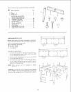
No. Table of Loose Parts Qty.
1 Leg ..................................... 4
2 Stiffener, L.H ............................. 4
3 Stiffener, R.H ............................. 4
Loose Parts Bag Part No. 63752
(containing the following items):
4 - Screw, Truss Hd. 1/4-20 x 5/8 .............. 40
5 - Lockwasher, 1/4 External ................. 40
5 - Lenkwasher, 5/16 External ................ 4
6 - Nut, Hex 1/4-20 ......................... 40
6 - Nut, Hex Jam 5/16-18 .................... 4
6 - Nat, Hex 1/2-13 ......................... 8
7 - Foot, Leveling .......................... 4
8 - Screw, Hex Hd. 5/16-18 x 5/8 .............. 4
9 Washer, 11/32 x 11/16 x 1/16 .............. 16
2
4
7
3
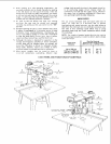
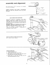
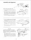
ASSEMBLING STEEL LEGS
NOTE: Steel Legs are furnished with Model 113_197751.
From among the loose parts, find the following Hardware:
40 Truss Head Screws. 1/4-20 x 5/8
40 Lockwashers, 1/4-External
40 Hex Nuts, 1/4-20
8 Hex Nuts, 1/2-13
4 Leveling Feet
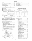
Assemble the Legs as shown.
1. Assemble Two (2) each of right and left hand Stiffeners
to the length shown using 1/4-20 x 5/8" truss head
screws, tockwashers and hex nuts.
2. Attach the four (4) legs to the Stiffeners using 1/4-20
screws, Iockwashers and nuts.
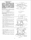
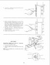
3. Install leveling feet as shown. To level steel legs, loosen
nut on inside of leg and turn nut on outside to raise or
lower feet. Adjust all four levelers if necessary, and then
tighten nuts on inside of leg.
intended for height
NOTE: These levelers are not
adjustment.
CAUTION: Leveling feet must be adjusted so the saw does
not rock AND so that the arm slopes slightly downward to
the rear so the carriage will not rotl forward due to gravity.
I°
I-
o o
o
STIFFENER
L.H.
0 0
0 0
STIFFENER
R.H.
O O
o
O
SflFFENER
L.H.
0 O t O O
I
I
O O II O O
i
STIFFENER
R.H.
3 2
1 2
1
°1
/
1