


assembJy
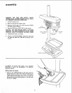
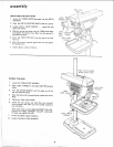
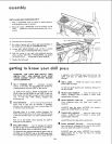
iNSTALLING AND TENSIONING BELT
1. Place a straightedge such as a piece of wood, metal or
framing square across the pulleys.
2. Move the motor UPWARDS until the pulleys are IN
LINE ... tighten the motor mounting nuts with a ½ in.
wrench.
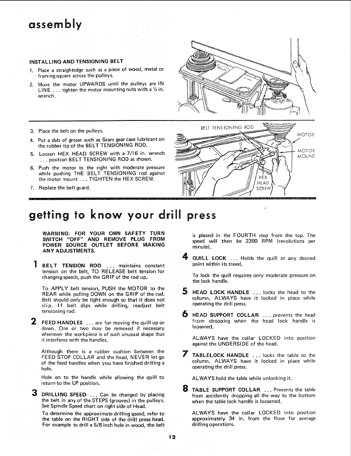
3. Place the belt on the pulleys.
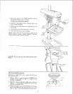
4. Put a dab of grease such as Sears gearcase lubricant on
the rubber tip of the BELT TENSIONING ROD.
5. Loosen HEX HEAD SCREW with a 7/16 in. wrench
... position BELT TENSIONING ROD as shown.
BELT TENSIONING ROD
MOTOR
MOTOR
MOUNT
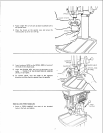
6. Push the motor to the right with moderate pressure
while pushing THE BELT TENSIONING rod against
the motor mount ... TIGHTEN the HEX SCREW. _/-_"
/
7. Replace the beltguard.
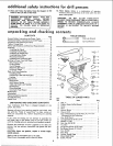
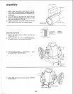
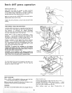
getting to know your driJJ press
WARNING: FOR YOUR OWN SAFETY TURN
SWITCH "OFF" AND REMOVE PLUG FROM
POWER SOURCE OUTLET BEFORE MAKING
ANY ADJUSTMENTS.
4
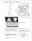
BELT TENSION ROD ... maintains constant
tension on the belt, TO RELEASE belt tension for
changing speeds, push the GRIP of the rod up.
2
To APPLY belt tension, PUSH the MOTOR to the
REAR while pulling DOWN on the GRIP of the rod.
Belt should only be tight enough so that it does not
slip. If belt slips while drilling, readjust belt
tensioning rod
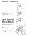
FEED HANDLES ... are for moving the quill up or
down. One or two may be removed if necessary
whenever the workpiece is of such unusual shape that
it interferes with the handles.
5
6
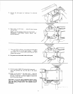
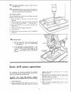
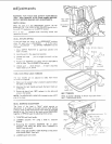
Although there is a rubber cushion between the
FEED STOP COLLAR and the head, NEVER let go
of the feed handles when you have finished drilling a
hole.
Hole on to the handle while allowing the quill to
return to the UP position.
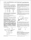
3 DRILLING SPEED ... Can be changed by placing
the belt in any of the STEPS (grooves) in the pulleys.
See Spindle Speedchart on right sideof Head.
To determine the approximate drilling speed, refer to
the table on the RIGHT side of the drill press head.
For example to drill a 5/8 inch hole in wood, the belt
7
8
is placed in the FOURTH step from the top. The
speed will then be 2300 RPM (revolutions per
minute).
QUILL LOCK ... Holds the quill at any desired
point within its travel.
To lock the quill requires only moderate pressure on
the lock handle.
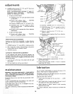
HEAD LOCK HANDLE ... locks the head to the
column. ALWAYS have it locked in place while
operating the drill press.
HEAD SUPPORT COLLAR ... prevents the head
from dropping when the head lock handle is
loosened.
ALWAYS have the collar LOCKED into position
against the UNDERSIDE of the head.
TABLELOCK HANDLE ... locks the table to the
column. ALWAYS have it locked in place while
operating the drill press.
ALWAYS hold the table while unlocking it.
TABLE SUPPORT COLLAR ... Prevents the table
from accidently dropping all the way to the bottom
when the table lock handle is loosened.
ALWAYS have the collar LOCKED into position
approximately 34 in. from the floor for average
drilling operations.
12