


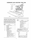
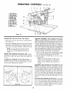
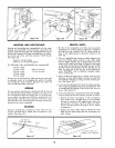
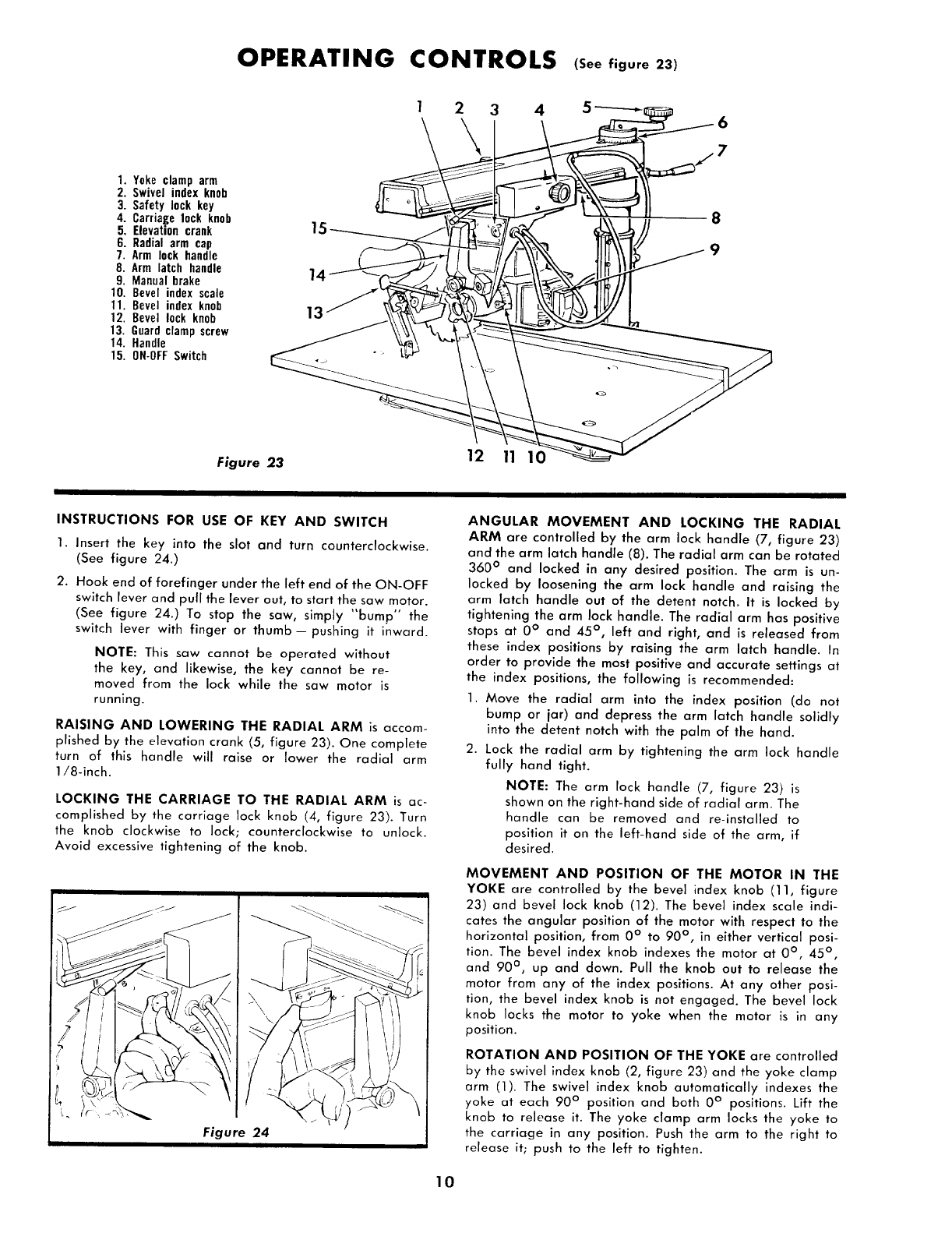
OPERATING CONTROLS (See figure 23)
1. Yoke clamp arm
2. Swivel index knob
3. Safety lock key
4. Carriagelock knob
5. Elevation crank
6. Radial arm cap
7. Arm lock handle
8. Arm latch handle
9. Manual brake
10. Bevel index scale
11. Bevel index knob
12. Bevel lock knob
13. Guardclamp screw
14. Handle
15. ON-OFFSwitch
1 2
Figure 23
3
12
4 5 -----_i_ 6
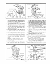
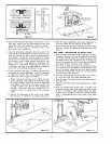
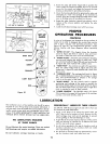
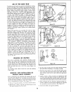
INSTRUCTIONS FOR USE OF KEY AND SWITCH
1. Insert the key into the slot and turn counterclockwise.
(See figure 24.)
2. Hook end of forefinger under the left end of the ON-OFF
switch lever and pull the lever out, to start the saw motor.
(See figure 24.) To stop the saw, simply _'bump °" the
switch lever with finger or thumb--pushing it inward.
NOTE: This saw cannot be operated without
the key, and likewise, the key cannot be re-
moved from the lock while the saw motor is
running.
RAISING AND LOWERING THE RADIAL ARM is accom-
plished by the elevation crank (5, figure 23). One complete
turn of this handle will raise or lower the radial arm
1/8-inch.
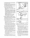
LOCKING THE CARRIAGE TO THE RADIAL ARM is ac-
complished by the carriage lock knob (4, figure 23). Turn
the knob clockwise to lock; counterclockwise to unlock.
Avoid excessive tightening of the knob.
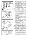
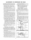
ANGULAR MOVEMENT AND LOCKING THE RADIAL
ARM are controlled by the arm lock handle (7, figure 23)
and the arm latch handle (8). The radial arm can be rotated
360 ° and locked in any desired position. The arm is un-
locked by loosening the arm lock handle and raising the
arm latch handle out of the detent notch. It is locked by
tightening the arm lock handle. The radial arm has positive
stops at 0 ° and 45 °, left and right, and is released from
these index positions by raising the arm latch handle. In
order to provide the most positive and accurate settings at
the index positions, the following is recommended:
1. Move the radial arm into the index position (do not
bump or jar) and depress the arm latch handle solidly
into the detent notch with the palm of the hand.
2. Lock the radial arm by tightening the arm lock handle
fully hand tight.
NOTE: The arm lock handle (7, figure 23) is
shown on the right-hand side of radial arm. The
handle can be removed and re-installed to
position it on the left-hand side of the arm, if
desired.
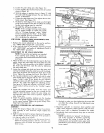
MOVEMENT AND POSITION OF THE MOTOR IN THE
YOKE are controlled by the bevel index knob (11, figure
23) and bevel lock knob (12). The bevel index scale indi-
cates the angular position of the motor with respect to the
horizontal position, from 0° to 90 °, in either vertical posi-
tion. The bevel index knob indexes the motor at 0 °, 45 ° ,
and 90 ° , up and down. Pull the knob out to release the
motor from any of the index positions. At any other posi-
tion, the bevel index knob is not engaged. The bevel lock
knob locks the motor to yoke when the motor is in any
position.
ROTATION AND POSITION OF THE YOKE are controlled
by the swivel index knob (2, figure 23) and the yoke clamp
arm (1). The swivel index knob automatically indexes the
yoke at each 90 ° position and both 0° positions. Lift the
knob to release it. The yoke clamp arm locks the yoke to
the carriage in any position. Push the arm to the right to
release it; push to the left to tighten.
10