


i
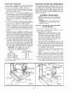
SWIVEL LATCH
PEN _ NOB ECCENTRIC SCREW
_[-'-_-/ _'t// aAM_
A/1M
LEFT SIDE OF CARRIAGE Figure 27
EC_ZENTRIC SCREW
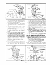
Figure 28
DARK
YE
GREEN
ORANGE
LIGHT
RED
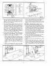
Figure 29
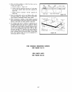
ECCENTRIC SCREW
CARRIAGE /
BEARING !/ AGE
LOCKWASHER \ WASHER
NUT
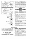
SET-UP
GUIDE
DEPTH OF CUT
ANGLE OF CUT
CARRIAGE LOCK
POWER CONTROL
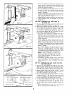
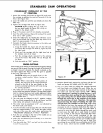
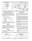
4. Rotate the yoke still farther (figure 28) to position the
cutout under the forward eccentric lock nut to provide
access for the wrench and adjust the forward carriage
bearing as described in preceding instructions.
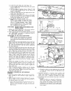
5. Check the bearing adjustment by grasping the yoke and
attempting to "rock" the carriage. If no movement is
evident, move the carriage along the radial arm to make
sure no binding occurs at any point on the arm.
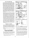
6. Rotate the yoke clockwise (viewed from above) until it
indexes at the crosscut position and tighten the yoke
clamp arm.
7. Install the left-hand carriage cover with two screws.
PROPER
OPERATING PROCEDURES
CONTROLS
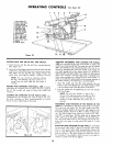
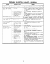
A series of six diagrams are located on the top surface of
radial arm in order to designate the controls that must be
used in basic "set-ups" and operating procedures. (See
figures 23 and 29.) The inexperienced operator should
become familia_ with these diagrams before operating
the saw.
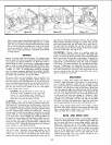
1. "'DEPTH OF CUT". The diagram shows the elevation
crank (5, figure 23) which is used to raise and lower
the blade. A clark blue circle is on the crank handle.
2. "'ANGLE OF CUT". Two levers are involved in releasing,
securing and indexing the angle of radial arm. These
are: arm lock handle (7, figure 23) and arm latch handle
(_8, figure 23), each marked with a yellow circle.
3. "'YOKE PIVOT". Two controls are used in this operation.
They are: swivel index knob (2, figure 23) and yoke
clamp arm (1, figure 23), each marked with a dark olive
green circle.
4. "'CARRIAGE LOCK". The carriage lock knob (4, figure
23), is rotated clockwise to secure the carriage on radial
arm, and counterclockwise to release it. An orange
circle is at the center of the knob.
5. "'BLADE ANGLE". The two controls used in angular
positioning and indexing of the motor to provide the
desired saw blade angle are: bevel lock knob (12, figure
23) and bevel index knob (11, figure 23). A light blue
circle is attached to each of these controls.
6. "POWER CONTROL". The ON-OFF switch (15, figure
23) is located in the upper left-hand area of the carriage
and has a red circle directly under it.
LUBRICATION
This Craftsman saw is a fine machine and should be given
the best of care. If kept clean and properly lubricated, it
will give many years of trouble-free service. Before describ-
ing the various points which may periodically require lubri-
cation, IT IS MORE IMPORTANT TO FIRST MENTION THE
VARIOUS SPOTS WHICH SHOULD NOT BE LUBRICATED.
NO LUBRICATION REQUIRED
AT THESE POINTS
Do not lubricate the motor bearings. These are sealed
ball bearings and require no added lubrication.
Do nat lubricate carriage bearings or tracks.
PERIODICALLY LUBRICATE THESE POINTS
Use SAE No. 10W-30 auto engine oil and refer to Parts List
for locations of parts listed below.
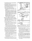
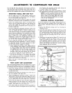
1. Apply a few drops of oil along the swivel index pin
only if the pin has a tendency to stick. Remove the left-
hand carriage cover and use oil sparingly to prevent
it from getting on the ball bearings or races.
2. A light film of oil can be wiped on the face of the column
tube and keyway to lubricate the fit between this part
and the key and column support.
3. An oil hole is provided in the top of elevation crank to
facilitate lubrication of the elevation shaft and radial
arm cap bearing surface.
4. The threads on elevation shaft are lubricated by remov-
ing the elevation crank and radial arm cap.
12