


7. Start the leveling screw into the T-nut on front table, but
do not allow the tip of the screw to protrude beyond the
bottom surface of front table.
8. Install Iockwashers and nuts on the six screws in the
table supports and tighten them finger tight. Start the
pan-head screw in the counterbored hole near the
center of front board into the U-nut on saw base, but
leave it approximately two turns loose.
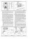
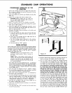
9. At this time the front table should be checked and ad-
justed at the center position as follows:
a. Move carriage to maximum rear position.
b. Using one edge of the rear table board as a straight-
edge, lay the board on the front table as shown
in figure 10.
c. Sight between edge of rear table and surface of front
table, to determine if the front table is low or high
at the center position. If front table is high, tighten
the center hold-down screw until it is level, then rotate
the leveling screw clockwise until it is "snug" against
the base front member. If the table is low at the
center, loosen the hold-down screw and rotate the
leveling screw clockwise until the front table is level,
then tighten the hold-down screw.
NOTE: After tightening screws, as described
above, always recheck to make sure that the
front table remains level. In some cases, a final
"touch-up" adjustment may be required.
STEP FOUR--SQUARING THE CROSS-CUT TRAVEL
1. Loosen the bevel lock knob, pull out on swivel index
knob and swivel the motor until the swivel index knob
indexes the motor with the shaft in a horizontal (zero)
position. Tighten the bevel lock knob.
2. Check to make sure the arm latch handle is securely
latched in the detent an_l the arm lock handle is still tight.
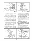
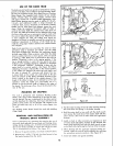
3. Install the saw blade as follows:
a. Place the inner collar on motor shaft. (See figure 4.)
b. Slide saw blade on motor shaft. Make sure teeth are
pointed in direction of saw rotation. (See figure 42
c. Install outer collar and arbor nut.
NOTE: The arbor shaft has left-hand threads.
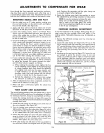
d. Usethe shaft wrench on motor shaft and arbor wrench
on arbor nut to tighten the nut, as shown in figure 11.
e. Lower the saw blade (with elevation crank) until the
blade isapproximately 1/32 inch above table surface.
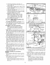
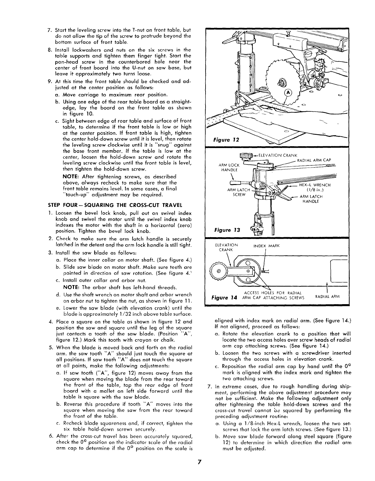
4. Place a square on the table as shown in figure 12 and
position the saw and square until the leg of the square
just contacts a tooth of the saw blade. (Position "A °',
figure 12.) Mark this tooth with crayon or chalk.
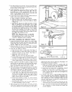
5. When the blade is moved back and forth on the radial
arm, the saw tooth "A '° should just touch the square at
all positions. If saw tooth "A" does not touch the square
at oil points, make the following adjustments:
a. If saw tooth ("A", figure 12) moves away from the
square when moving the blade from the rear toward
the front of the table, tap the rear edge of front
board with a mallet on left side forward until the
table is square with the saw blade.
b. Reverse this procedure if tooth "A" moves into the
square when moving the saw from the rear toward
the front of the table.
c. Recheck blade squareness and, if correct, tighten the
six table hold-dawn screws securely.
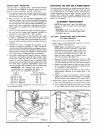
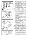
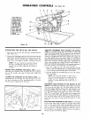
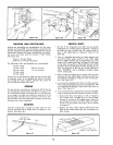
6. After the crass-cut travel has been accurately squared,
check the 0° position on the indicator scale of the radial
arm cap to determine if the 0° position on the scale is
Figure 12 _ _ -
i
J_]_.-,,_- ELEV AT IO N CRANK
ARM LO _ -- _ j RADIAL ARM CAP
CK i "_
HANDLE _ _
l _ HANDLE
Figure 13 _ ! _
ELEVATION INDEX MARK
ACCESS HOLES FOR RADIAL
Fjgure 14 ARM CAP AIi"ACHING SCREWS
,L
RADIAL ARM
aligned with index mark on radial arm. (See figure 14.)
If not aligned, proceed as follows:
a. Rotate the elevation crank to a position that will
locate the two access holes over screw heads of radial
arm cap attaching screws. (See figure 14.)
b. Loosen the two screws with a screwdriver inserted
through the access holes in elevation crank.
c. Reposition the radial arm cap by hand until the 0 °
mark is aligned with the index mark and tighten the
two attaching screws.
7. In extreme cases, due to rough handling during ship-
ment, performing the above adjustment procedure may
not be sufficient. Make the following adjustment only
after tightening the table hold-down screws and the
cross-cut travel cannot be squared by performing the
preceding adjustment routine:
a. Using a 1/8-inch Hex-L wrench, loosen the two set-
screws that lock the arm latch screws. (See figure 13.)
b. Move saw blade forward along steel square (figure
12) to determine in which direction the radial arm
must be adjusted.
7