


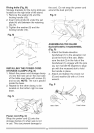

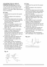

o Thebladebodymustbethinnerthan
thethicknessoftherivingknifebut
thebladekerfmustbethickerthan
therivingknife.
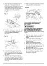
7. Checktherivingknifeandblade
alignmentagainatboth0° and45°.
8. Replacethetableinsert,bladeguard
andanti-kickbackpawlassembly.
Fig. X
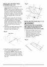
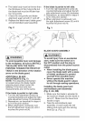
i_ WARNING]
To avoid possible injury and damage
to the workpiece, be sure to INSTALL
THE BLADE WITH THE TEETH
POINTING TOWARD THE FRONT OF
TABLE in the direction of the rotation
arrow on the blade guard.
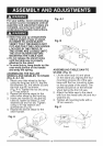
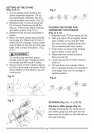
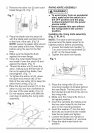
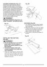
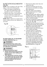
ADDITIONAL BLADE
ADJUSTMENTS (Fig. Y)
NOTE: The adjusting mechanism
is located above the blade height
adjusting hand wheel under the
tabletop. If the front and rear
measurements are not the same.
If the blade is partial to right side:
1. Turn the left adjustment screw (2)
counterclockwise and adjust the right
side adjustment screw (3) clockwise.
2. Remeasure, as described in steps 4
to 9 in the prior section.
3. When alignment is achieved, turn
the left adjustment screw (2) until it
touches the pivot rod (4).
If the blade is partial to left side:
1. Turn the right adjustment screw (3)
counterclockwise and adjust the left
side adjustment screw (2) clockwise.
2. Remeasure, as described in steps 4
to 9 in the prior section.
3. When alignment is achieved, turn
the right adjustment screw (3) until it
touches the pivot rod (4).
Fig. Y
4
BLADE GUARD ASSEMBLY
I,A WARNING l
To avoid injury from an accidental
start, make sure the switch is in
the OFF position and the plug is
disconnected from the power source
outlet.
o When installing the blade guard,
cover the blade teeth with a piece
of folded cardboard to protect
yourself from possible injury.
o Never operate this machine
without the blade guard in place
for all through sawing operations.
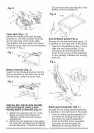
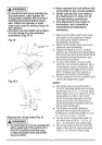
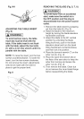
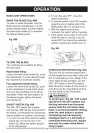
Installing the blade guard and
anti=kickback pawl assembly
(Fig. Z, AA, BB)
1. Make sure the blade is elevated to
its maximum height and the bevel is
set at 0°. Make sure the bevel lock
handle is tight.
2. Take the anti-kickback pawl
assembly (1) and locate the red
sliding knob and push the locking
knob (2) up. (Fig. Z)